Table of Contents
Advertisement
Quick Links
Advertisement
Table of Contents

Related Manuals for Sper scientific AquaShock 850034K


Summary of Contents for Sper scientific AquaShock 850034K
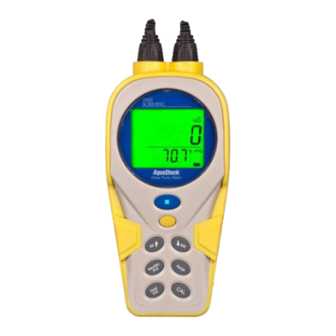
- Page 1 AquaShock® Water Purity Kit 850034K...
- Page 2 Sper Scientific. Sper Scientific 8281 E. Evans Rd., Suite #103, Scottsdale, AZ 85260 Tel: (480) 948-4448 Fax: (480) 967-8736 Web: www.sperscientific.com...
-
Page 3: Table Of Contents
TABLE OF CONTENTS INTRODUCTION ........4 FEATURES. -
Page 4: Introduction
Lithium Ion battery. The meter is highly accurate and stable, very intuitive and includes all of the functions required by most users. Sper Scientific guarantees you will not find any meters more rugged and reliable than AquaShock®. -
Page 5: Features
FEATURES • Floats • Shockproof • IP67 Waterproof • Protective soft grip outer layer • Rechargeable Lithium Ion battery • Also accepts standard BNC probes • Multi-line display LCD screen • Reads Conductivity and TDS • Auto Ranging • Automatic Temperature Compensation •... -
Page 6: Lcd Display
LCD DISPLAY Name Description Ready Displayed when measuring results are stable Scale Unit Current measurement scale unit Measuring Results Current measurement value Automatic Temperature Compensation indicator Temperature Scale Current temperature measurement unit Temperature Value Current temperature measurement value Battery Icon Current battery power level... -
Page 7: Power Supply
LCD DISPLAY Probe Life Icon: More than 90% life remaining More than 85 –90% life remaining More than 80 -85% life remaining Less than 80% life remaining Battery Power Icon: Battery voltage is more than 7.7V shows full. Battery voltage between 7.2V and 7.7V shows 2 cells. Battery voltage between 6.6V and 7.2V shows 1 cell. -
Page 8: Keypad
KEYPAD Water Purity Meter Name 1st Function 2nd Function Power/Backlight/ Power on/off Backlight on/off Low Battery Setup Setting parameters Confirm setting MI↑ Store data ↑ MR↓ Recall data ↓ Max/Min/Ave Max/Min/Ave Range Switch measuring scale Hold/Exit Hold Exit Calibration... -
Page 9: Setup Mode
SETUP MODE The Setup Mode allows you to customize the following meter preferences and defaults: • Temperature Scale • Clock Setting • Restore Factory Defaults • Set ATC Temperature Coefficient • Set TDS Factor 1. Press POWER to turn the meter on before performing any setup function. - Page 10 Press SETUP to save and the meter automatically moves to the month setting (see Fig. C.). 5. Repeat step 4 to adjust the month, day, hour, and minute (see Fig. D, E & F). 6. Press EXIT to return to Normal Mode without saving. Note...
- Page 11 Restore Factory Settings 1. Press SETUP to enter the Setup Mode. 2. Press ↑ or ↓ to select the Restore Factory Settings screen (see Fig. A). 3. Press SETUP to confirm selection. “NO” will flash on the LCD. (see Fig. B). 4.
- Page 12 Set ATC Temperature Coefficient 1. Press SETUP to enter the Setup Mode. 2. Press ↑ or ↓ to select the Set Temperature Coefficient screen (See Fig. A.). 3. Press SETUP to enter the Set Temperature Coefficient screen. The current value setting will flash (see Fig. B). 4.
- Page 13 Set TDS Factor 1. Press SETUP to enter the Set up mode. 2. Press ↑ or ↓ to select the Set TDS Factor screen (see Fig. A). 3. Press SETUP to enter the mode, the current value setting will flash (see Fig. B). 4.
-
Page 14: Calibration
CALBRATION Before calibration, place the probe in the standard calibration solution. If measured values exceed the standard solution concentration by ±20%, re-clean your probe or replace it. Conductivity Calibration Press RANGE to choose the conductivity scale. 1. Press CAL for 2 seconds to enter the calibration mode. The meter will automatically select the correct range. -
Page 15: Tds Calibration
TDS Calibration Press RANGE to choose the TDS scale. 1. Press CAL for 2 seconds to enter the calibration mode. The meter will automatically select the correct range. The measured value is displayed above the line, the set calibration value is shown flashing below the line (see Fig. A). 2. - Page 16 View Calibration Points 1. Press RANGE to choose the scale you wish to view. 2. Press SETUP to enter the Setup Mode. 3. Press ↑ or ↓ to select the View Cal Data screen (see Fig. A). 4. Press SETUP to enter the View Cal Data Mode. The date and time is a cyclic display (the Conductivity scale will display as in Fig.
-
Page 17: Measurement Procedures
MEASUREMENT PROCEDURES Note… If the ATC Temperature Probe is not connected, the display will read as in Fig. A. No measurement can be performed until the ATC jack is connected. Fig. A Auto Ranging: The meter will measure conductivity in the μS/cm and mS/cm scales and will calculate the TDS value in ppm or ppt according to the TDS conversion coefficient that was entered in the TDS Factor set up procedure. - Page 18 Turning the Meter On/Off 1. Press POWER to turn the meter on. The meter will default to the last used measurement and temperature scales. 2. Press and hold POWER for 2 seconds to turn the meter off. Indicator Light Descriptions Meter Status Indicator Status Power off...
- Page 19 Saving to Memory 1. Press MI to save the current measured value and view the data point number (see Fig. A). 2. Up to 99 Memories can be saved for both Conductivity and TDS. If the saved memory exceeds 99, the new data will be written over saved memories beginning with #1.
- Page 20 Recall Memory 1. Press RANGE to select the scale for recall. 2. Press MR to enter the Recall mode and view the last saved reading (see Fig. A and Fig. B). The date and time are on cyclical display. If there is no saved data “- - - -“ is displayed (see Fig.
- Page 21 Clear Memory 1. Press MI and MR simultaneously for 2 seconds to clear all memory (see Fig. A). The meter will return to Normal mode. Fig. A Hold 1. Press HOLD to hold the value (see Fig. A). 2. Press HOLD to release the hold value. Note…...
- Page 22 Maximum, Minimum and Average 1. Press RANGE to select the scale. 2. Press MAX/MIN/AVE, the maximum recorded value will appear on the LCD (see Fig. A and Fig. B. The date and time are on cyclical display, If no measurements have been taken, “- - - -”...
-
Page 23: Specifications
Fig. E Fig. F SPECIFICATIONS Mode Temperature Conductivity Range 32 to 212°F 0 to 19.99 μS 0.0 to 9.99 ppm 0 to 100°C 0 to 199.9 μS 10.0 to 99.9 ppm 0 to 1999 μS 100 to 999 ppm 0 to 19.99 mS 1.0 to 9.99 ppt 0 to 199.9 mS 10.0 to 199.9 ppt... -
Page 24: Warranty
WARRANTY Sper Scientific warrants this product against defects in materials and workmanship for a period of five (5) years from the date of purchase, and agrees to repair or replace any defective unit without charge. If your model has since been discontinued, an equivalent Sper Scientific product will be substituted if available.
Need help?
Do you have a question about the AquaShock 850034K and is the answer not in the manual?
Questions and answers