Advertisement
Quick Links
Advertisement

Related Manuals for CEM 722-449


Summary of Contents for CEM 722-449
- Page 1 OPERATING INSTRUCTION 1000A True RMS DC/AC CLAMP METER...
-
Page 2: Safety Notes
Safety International Safety Symbols This symbol, adjacent to another symbol or terminal, indicates the user must refer to the manual for further information. This symbol, adjacent to a terminal, indicates that, under normal use, hazardous voltages may be present Double insulation SAFETY NOTES Do not exceed the maximum allowable input range of any function... - Page 3 operating the meter. Always remove the test leads before replacing the battery. Inspect the condition of the test leads and the meter itself for any damage before operating the meter. Repair or replace any damage before use. Use great care when making measurements if the voltages are greater than 25VAC rms or 35VDC.
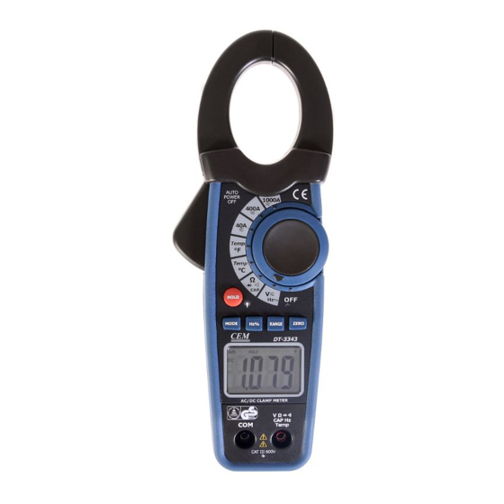
- Page 4 Meter Description 1. Current clamp 2. Clamp trigger 3. Data Hold and Backlight button 4. Mode select button 5. Hz/% button 4 0 0 A 4 0 A 6. LCD display 7. COM input jack 8. Rotary Function swith ¡ ã ¡...
-
Page 5: Specifications
Specifications Function Range & Accuracy Resolution reading) ± (2.8% + 10 40.00 AAC digits ± (2.8 % + 5 DC Current 400.0 AAC digits ± (3.0 % + 5 1000 AAC digits ± (3.0% + 10 40.00 AAC digits AC Current ±... - Page 6 100.0μ F (5.0% reading digits) Frequency 5.000Hz (1.5% reading + 5 digits) 50.00Hz (1.2% reading digits) 500.0Hz Sensitivity: 10Vrms 5.000kHz min. 50.00kHz 100.0kHz Duty Cycle 0.5 to 99.0% (1.2% reading + 2 digits) Pulse width: 100µs - 100ms, Frequency: 5.000Hz ~ 100.0kHz Temp (type- -20 to 1000 C (3.0% reading + 5 C)
- Page 7 True RMS: The term stands for “Root-Mean-Square,” which represents the method of calculation of the voltage or current value. Average responding multimeters are calibrated to read correctly only on sine waves and they will read inaccurately on non- sine wave or distorted signals. True rms meters read accurately on either type of signal.
-
Page 8: Operation
Operation NOTICES: Read and understand all warning and precaution statements listed in the safety section of this operation manual prior to using this meter. Set the function select switch to the OFF position when the meter is not in use. DC/AC Current Measurements WARNING: Ensure that the test leads disconnected from the meter before... - Page 9 4. Connect the test leads in parallel to the circuit under test. 5. Read the voltage measurement on the LCD display. Resistance and Continuity Measurements Insert the black test lead into the negative COM terminal and the red test lead into the positive terminal. •))) Set the function switch to the position.
- Page 10 indicate “OL”. Shorted devices will indicate near 0mV and an open device will indicate “OL” in both polarities. Black Black Probe Probe Probe Probe Forward test Reverse test Capacitance Measurements WARNING: To avoid electric shock, disconnect power to the unit under test and discharge all capacitors before taking any capacitance measurements.
- Page 11 Temperature Measurements WARNING: To avoid electric shock, disconnect both test probes from any source of voltage before making a temperature measurement. Set the function switch to TEMP. Insert the Temperature Probe into the negative (COM) and the V jacks, making sure to observe the correct polarity.
- Page 12 second to turn the backlight on and press the button a second time to turn the backlight off. Manual Ranging The meter turns on in the autoranging mode. Press the Range button to go to manual ranging. Each press of the range button will step to the next range as indicated by the units and decimal point location.
Need help?
Do you have a question about the 722-449 and is the answer not in the manual?
Questions and answers