Table of Contents
Advertisement
Quick Links
I. Safety Information
The following safety information must be observed to insure maximum
personal safety during the operation at this meter:
Do not use the meter if the meter or test leads look damaged, or if you
suspect that the meter is not operating properly.
Never ground yourself when taking electrical measurements. Do not
touch exposed metal pipes, outlets, fixtures, etc., which might be at
ground potential. Keep your body isolated from ground by using dry
clothing, rubber shoes, rubber mats, or any approved insulating material.
Turn off power to the circuit under test before cutting, unsoldering, or
breaking the circuit. Small amounts of current can be dangerous.
Use caution when working above 60V dc or 30V ac rms. Such voltages
pose a shock hazard.
When using the probes, keep your fingers behind the finger guards on
the probes.
Measuring voltage which exceeds the limits of the multimeter may
damage the meter and expose the operator to a shock hazard. Always
recognize the meter voltage limits as stated on the front of the meter.
SAFETY SYMBOLS
! Indicates operators must refer to the explanation in this manual.
Indicates terminals at which dangerous voltage maybe present.
1
WARNING
To avoid electrical shock hazard or damage to the meter, Don't apply input
which exceed the limit shown below:
Function
Terminal
DCV/ACV
"V/
/Hz"
Ω
/Continuity/Diode/Cap. "V/
Ω
/
Freq / Duty
"V/
Hz"
Ω
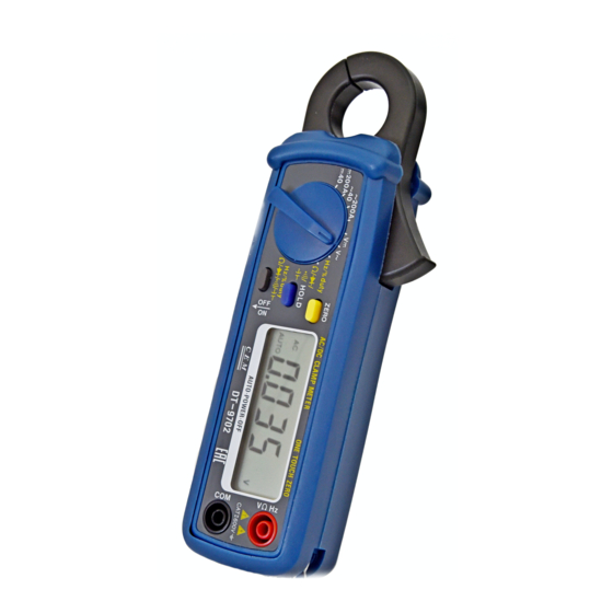
II. Features
1. Accurate DC/AC digital clamp meter for current measurement.
2. 10mA high resolution on 40A DC/AC range.
3. One touch zero adjustment for DC Current measurement.
4. 23mm diameter jaw.
5. 4000 counts LCD display with function indication
6. 40A, 200A DCA/ACA clamp meter with function of DCV, ACV, OHM,
Frequency,
Duty
cycle,
measurements.
7. Auto-ranging for DC/AC voltage, Resistance, Frequency, Duty cycle
and Capacitance measurement.
8. Auto power off
9. Data Hold function
Input limits
600V dc or ac rms.
/Hz" 250V dc or ac rms.
Ω
250V dc or ac rms.
Diode,
Capacitance
and
2
Continuity
Advertisement
Table of Contents

Related Manuals for CEM 9702


Summary of Contents for CEM 9702
- Page 1 I. Safety Information WARNING The following safety information must be observed to insure maximum To avoid electrical shock hazard or damage to the meter, Don’t apply input personal safety during the operation at this meter: which exceed the limit shown below: Do not use the meter if the meter or test leads look damaged, or if you Function Terminal...
- Page 2 Ⅲ. Panel Description 8. Low Battery Symbol 1. Transformer Jaw When this symbol appears, it means the battery voltage drops below the This is used to pick up current signal. To measure DC/AC current, minimum required voltage. Refer to Section V for battery replacement conductor must be enclosed by the jaw 9.
- Page 3 Measurement rate: 2 times per second, nominal. DC Voltage (Auto-ranging) Range Resolution Accuracy Auto power off : Meter automatically shuts down after approx. 30 minutes of 400.0mV 0.1mV ±0.8% of rdg±2 dgts inactivity. 4.000V 40.00V 10mV ±1.0% of rdg±2 dgts Operating environment: 0℃...
- Page 4 Capacitance (Auto-ranging) Diode Test Range Resolution Accuracy Test current Resolution Accuracy 4.000nF ±6.0% of rdg±15 dgts 0.3 mA typical 1 mV ±10% of rdg±5 dgts 40.00nF 10pF ±6.0% of rdg±10 dgts Open circuit voltage: 1.5V dc typical 400.0nF 0.1nF 4.000uF ±3.5% of rdg±5 dgts Overload protection: 250V dc or ac rms.
- Page 5 Hz/% OR OHM/DIODE/CONTINUITY/CAPACITANCE SELECTING measured. No air gap is allowed between the two half jaws. BUTTON: Read the measured value from the LCD display. Push this button to select ohm/diode/continuity/capacitance measuring Make sure that the offset value caused by the residual magnetism is function when the function switch is set at ohm/diode/buzzer/capacitance still removed.
- Page 6 Insert the test leads into the input jack. 8. When measuring the forward voltage across diode a normal diode will Connect the test probe in parallel to the circuit to be measured. indicate 0.4V to 0.7V and the reverse voltage will indicate “OL” (same Read the measured value from the LCD display.
- Page 7 DCAC CLAMP METER NOTE: The input voltage should be between 900mV and 10V rms. If the voltage is Model 9702 more than 10V rms., reading may be out of the accuracy range. OPERATING INSTRUCTION Ⅵ. Battery Replacement When the low battery symbol is displayed on the LCD, replace the old battery with one new battery.
- Page 8 TABLE OF CONTENTS Ⅰ. Safety Information Ⅱ. Features Ⅲ. Panel Description Ⅳ. Specifications Ⅴ. Operation Instructions DC/AC Current Measurements DC/AC Voltage Measurements Resistance, Diode, Continuity and Capacitance Measurement Frequency and Duty Cycle Measurement Ⅵ. Battery Replacement...
Need help?
Do you have a question about the 9702 and is the answer not in the manual?
Questions and answers