Intermatic P1353ME Instruction Manual
Multipurpose control
Hide thumbs
Also See for P1353ME:
- Instruction manual (40 pages) ,
- Installation, operation & service manual (4 pages) ,
- Instruction manual (21 pages)
Table of Contents
Advertisement
Quick Links
Download this manual
See also:
Instruction Manual
http://waterheatertimer.org/Digital-control-centers-and-manuals.html#P1353ME
INSTRUCTION MANUAL
INTERMATIC
MULTIPURPOSE CONTROL
MECHANISM MODEL: P1353ME
ATTENTION
READ CAREFULLY BEFORE ATTEMPTING TO
INSTALL YOUR INTERMATIC MULTIFUNCTION
CONTROL SWITCH. FAILURE TO COMPLY WITH
INSTRUCTIONS COULD RESULT IN PERSONAL
INJURY AND/OR PROPERTY DAMAGE! RETAIN
FOR FUTURE REFERENCE.
1-Year Limited Hardware Warranty
If within the warranty period specified, this product fails
due to a defect in material or workmanship, Intermatic
Incorporated will repair or replace, at its sole option, the
unit free of charge. This warranty applies only to the
original purchaser and is not transferable. This warranty
does not apply to: (a) damage caused by accident,
abuse, mishandling, dropping, acts of God, or any
negligent use; (b) units which have been subject to
unauthorized repair, opened, taken apart, or otherwise
modified; (c) units not used in accordance with instruc-
tions; (d) damages exceeding the cost of the product.
Some states do not allow a limitation of damages, so the
foregoing limitation may not apply to you. This warranty
gives you specific legal rights and you may have other
rights that vary from state to state. INTERMATIC INCOR-
PORATED WILL NOT BE LIABLE FOR INCIDENTAL OR
CONSEQUENTIAL DAMAGES. THIS WARRANTY IS IN
LIEU OF ALL OTHER EXPRESS OR IMPLIED WAR-
RANTIES. ALL IMPLIED WARRANTIES, INCLUDING
THE WARRANTY OF MERCHANTABILITY AND THE
WARRANTY OF FITNESS FOR A PARTICULAR
PURPOSE, ARE HEREBY MODIFIED TO EXIST ONLY
AS CONTAINED IN THIS LIMITED WARRANTY, AND
SHALL BE OF THE SAME DURATION AS THE
WARRANTY PERIOD STATED ABOVE. This warranty
service is available by either (a) returning the product to
the dealer from whom the unit was purchased, or (b)
mailing postage prepaid to the nearest authorized service
center listed.
Please be sure to wrap the product
securely when mailing to avoid shipping damage. This
warranty is made by: Intermatic Incorporated – After
Sales Service, 7777 Winn Road, Spring Grove, Illinois
60081-9698 phone: (815) 675-7000
AFTER SALES SERVICE – INTERMATIC INCORPORATED
http://www.intermatic.com
7777 Winn Road, Spring Grove, Illinois 60081-9698
158PE11693
Advertisement
Table of Contents

Related Manuals for Intermatic P1353ME


Summary of Contents for Intermatic P1353ME
- Page 1 INSTRUCTION MANUAL 1-Year Limited Hardware Warranty If within the warranty period specified, this product fails due to a defect in material or workmanship, Intermatic INTERMATIC Incorporated will repair or replace, at its sole option, the unit free of charge. This warranty applies only to the MULTIPURPOSE CONTROL original purchaser and is not transferable.
-
Page 2: Table Of Contents
Control Panel ......14,15 existing Intermatic panel or rain tight enclosure in the Step #6 Ratings, Wiring Schematics industry today. -
Page 3: Warning And General Safety Information
Control, Freeze Probe), prior to installing the Multi- 1. Follow all local electrical and safety codes, National purpose Control into an Intermatic control center. Electric Code (NEC), as well as Occupational Safety Refer to pages 6 and 7 for further accessory details. - Page 4 IDENTIFY LOW VOLTAGE ACCESSORY CONNECTIONS AND SET PROPER VOLTAGE SELECTION Freeze Probe Connection – This connector is where you would connect the Intermatic Freeze Sensor Part Number 178PA28A (optional). It needs to be installed in order for the freeze protection circuit and programming to work.
-
Page 5: Step #2 Installing The Shutter Bushing
STEP #3 STEP #2 ROUTE ACCESSORY WIRES AND INSTALLING THE SHUTTER BUSHING CONNECTORS INTO ENCLOSURE AND CONNECT TO THEIR PROPER LOCATIONS Control Center Installation Procedure 1. Push the Firemen Switch wires and/or the Freeze Sensor Cable through the installed Shutter Bushing and into the control center. -
Page 6: Remote Control
(i.e. 120V or 240V), you intend to use for powering the Multipurpose Control. This jumper is located on 2. Depending on your particular Intermatic Control the back of the control (See Figure #1 for location Center and low voltage accessories to be installed, and setting). -
Page 7: Mode Table
Remote You should have now completed Control is not installed, only one corrugated tube is necessary. installing the Intermatic Multipurpose Retainer Control and available accessories. Prior to wiring the equipment to the control, you should read and understand Step... -
Page 8: An Overview Of The Multipurpose Control Panel
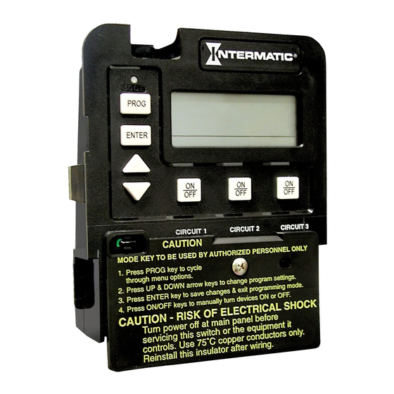
AN OVERVIEW OF THE MULTIPURPOSE CONTROL PANEL DISPLAY MODE BUTTON Indicates time of day With a small tool, press and hold this button down for and programming settings 5 seconds. Using the Up and Down arrow keys, you during programming mode. can select the appropriate preprogrammed mode that matches your particular pool or spa equipment pad configuration. -
Page 9: Mode
STEP #6 Defining & Wiring Each Mode Mode 1 – (Aux1, Aux2, Aux3) Each of the three single MULTIPURPOSE CONTROL pole circuits are defined generically, and can control any RATINGS, WIRING AND SETTING THE MODE load within each of its individual circuit ratings. All three IMPORTANT NOTE There are five modes to choose from depending on circuits act independent of each other. - Page 10 Mode 2 – (Pump High, Pump Low, Aux3) Circuit one Mode 3 – (Pump, Aux2, Cleaner Pump) Circuit one and two are dedicated single pole outputs for a two- and three are dedicated single pole outputs for a single speed pump load. Circuits one and two will never be speed pump working with a pressure side cleaner ON at the same time, consistent with a two-speed pump pump.
-
Page 11: (Pump High, Pump Low, Cleaner Pump)
Mode 4 – (Pump High, Pump Low, Cleaner Pump) Mode 5 – (Pump, Pump, Aux3) Circuit one and two Circuit one and two are dedicated single pole outputs are now coupled together making up one circuit capable for a two-speed pump load. Circuits one and two will of switch both poles of a power source. -
Page 12: Setting The Mode
STEP #7 Setting The Mode Setting The Time 1. With a small pointed tool, (i.e. pen, pencil, screw- driver, etc…) Press and hold the Mode Button (Approximately 5 seconds) until the display shows 1. Press and release the program key. The displayed SET MODE and the Mode Number blinks. - Page 13 STEP #8 3. Once you are satisfied with the start time, press and release the Enter Key. You have now saved the start Setting On/Off Times for Each Circuit time, and the display will prompt you for the desired Stop time for circuit #1’s 1st event. 1.
- Page 14 All manual ON operations for circuits 1 & 2 override all IMPORTANT NOTE CONCERNING SETTING programmed ON times. Therefore, any desired low and THE ON/OFF TIMES FOR EACH MODE high-speed run combinations need to be programmed as separate events and not controlled by combining the 1.
-
Page 15: Step#9 Setting The Firemen Switch Time
The freeze temperature programming will not appear The cool down time is a time defined by the program- unless you have installed the Intermatic freeze sensor, mer. It’s used in conjunction with a pool heater, (See Fig. #1 for installation and ordering details). -
Page 16: Runtime Definitions
Runtime Definitions Freeze Control Runtime Display Firemen Switch Runtime Display The following example illustrates how the display will The following example illustrates how the display will look when the freeze control feature is activated. In this look when the cool down feature is activated. In this example, the freeze sensor was connected, enabling example, the cool down time was set for 5 minutes, the freeze control feature. - Page 17 It may be necessary to view the revision level of the now use the arrow keys to modify the current runtime. internal programming for service purposes, or compati- bility issues with future Intermatic Designs. To do so, Clearing all scheduled ON/OFF simply follow the below procedure:...
-
Page 18: Cleaner Pump Runtime Display
Special Features Cleaner Pump Runtime Display Setting The The cleaner pump should always be connected to circuit Countdown Timer #3 and the mode setting should be set to #3 or #4, depending on the filter pump configuration. Before the The countdown or runtime timer allows you to turn on a cleaner pump can come on, circuit #1 (filter pump) must desired load for a predefined amount of time without be on for more than 30 seconds.
Need help?
Do you have a question about the P1353ME and is the answer not in the manual?
Questions and answers