Advertisement
Quick Links
Installation and Setup Instructions
WARNING
Risk of Fire or Electric Shock
• Disconnect power at the circuit breaker(s) or disconnect switch(es) before beginning installation or servicing.
• Do NOT use the OFF state of the photocontrol for equipment servicing.
NOTICE
NOTICE
• DO NOT MOUNT WITH THE WIRES FACING UP.
Ratings:
Refer to product unit label for load rating information
:
Installation
1. Make sure to turn the power off at the breaker before installation.
2. Mount with an approved outdoor junction box or fixture using the included gasket and nut. (See photo)
DO NOT MOUNT WITH THE WIRES FACING UP OR ON THE BOTTOM OF AN ENCLOSURE.
3. Orient the lens of the photocontrol so it faces NORTH and away from artificial light sources that may cause the load to
turn off at night.
4. See diagram for wiring.
5. When all wiring is complete, you can turn the breaker back on to restore power to the photocontrol.
6. Test the unit by covering the lens of the photocontrol with a leather glove or similar. The photocontrol should react to a change within
60 seconds.
Instructions d'installation et de configuration
AVERTISSEMENT
Risque d'incendie ou d'électrocution
• Débrancher l'alimentation au niveau des disjoncteurs ou des sectionneurs avant de procéder à l'installation ou à l'entretien.
• Ne PAS utiliser l'état ARRÊT de la commande photo-électronique pour travailler sur le matériel.
AVIS
AVIS
• NE PAS MONTER AVEC LES FILS VERS LE HAUT.
Notes :
Reportez-vous à l'étiquette de l'unité du produit pour obtenir des informations sur la capacité de charge.
:
Installation
1. Veiller à couper l'alimentation au niveau du disjoncteur avant de procéder à l'installation.
2. Effectuer le montage à l'aide d'une boîte de dérivation ou un luminaire homologués pour l'extérieur à l'aide du joint et de l'écrou
fournis (Voir photo)
NE PAS MONTER AVEC LES FILS ORIENTÉS VERS LE HAUT OU VERS LE BAS D'UN BOÎTIER.
3. Orienter la lentille de la commande photo-électronique de sorte qu'elle soit orientée vers le NORD et à l'écart de sources de lumière
artificielle susceptibles de provoquer l'ouverture du circuit de charge la nuit.
4. Voir le schéma de câblage.
5. Une fois le câblage terminé, il sera possible de remettre le disjoncteur en marche pour rétablir l'alimentation dans la commande
photo-électronique.
6. Pour vérifier le fonctionnement, couvrir la lentille de la commande photo-électronique avec un gant de cuir ou un produit similaire. La
commande photo-électronique doit réagir à ce changement au bout de 60 secondes.
Instalación e instrucciones de configuración
ADVERTENCIA
Riesgo de incendio o descarga eléctrica
• Desconecte la alimentación eléctrica de los disyuntores o desconecte los interruptores antes de comenzar la instalación o el mantenimiento.
• NO use el estado OFF (apagado) del control fotoelectrónico para realizar mantenimiento del equipo.
AVISO
AVISO
• NO LO MONTE CON LOS CABLES HACIA ARRIBA.
Calificaciones:
Consulte la etiqueta de la unidad del producto para obtener información sobre la capacidad de carga.
Instalación:
1. Asegúrese de desconectar la alimentación eléctrica en el disyuntor antes de la instalación.
2. Monte con una caja de conexiones o luminaria aprobada para exteriores con la junta y la tuerca incluidas. (Ver foto)
NO MONTE CON LOS CABLES HACIA ARRIBA O EN LA PARTE INFERIOR DE UN RECINTO.
3. Oriente la lente del control fotoelectrónico de forma que apunte al NORTE y lejos de fuentes de luz artificiales que puedan provocar que la
carga se apague por la noche.
4. Consulte el diagrama a continuación para ver el cableado.
5. Cuando todo el cableado esté completo, puede volver a activar el disyuntor para restablecer la alimentación eléctrica del
control fotoelectrónico.
6. Para probar la unidad, cubra la lente del control fotoelectrónico con un guante de cuero o similar. El control fotoelectrónico debe reaccionar al
cambio en el transcurso de 60 segundos.
Mounting Options/ Options de montage/ Opciones de montaje
GASKET
JOINT
JUNTA
NUT
ÉCROU
TUERCA
GASKET
JOINT
JUNTA
Accessories: Use when there is a high amount of incident light on the photocontrol from artificial light sources that may interfere with proper operation of photocontrol.
Accessoires: À utiliser si la commande photo-électronique est exposée à une grande quantité de lumière incidente provenant de sources de lumière artificielle susceptibles de nuire à son bon fonctionnement.
Accesorios: Se debe usar donde hay una gran cantidad de luz incidente en el control fotoelectrónico proveniente de fuentes de luz artificiales que puedan interferir con el funcionamiento correcto del control
fotoelectrónico.
MODEL K4000, ELC4000, EK4000 Series
MODÈLE Série K4000, ELC4000, EK4000
MODELO serie K4000, ELC4000, EK4000
NUT
ÉCROU
TUERCA
Line 1 - Input
From Breaker
or
Power Source
Neutral
or
(if 120/277/347 Vac)
(if 208/240/480 Vac)
Ligne 1 - Entrée
Du disjoncteur
ou de la source
d'alimentation
Neutre
ou
(si 120/277/347 V CA)
(si 208/240/480 V CA)
Línea 1 - Entrada
Desde el
disyuntor o
fuente de
alimentación
Neutro
(si 120/277/347 V CA)
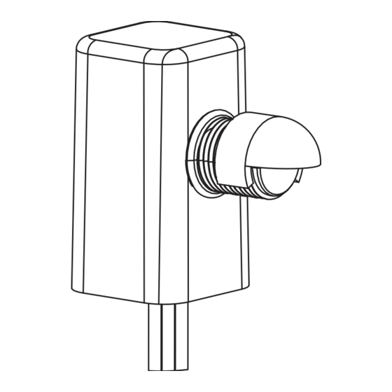
Accessories/ Accessoires/ Accesorios
LIGHT SHIELD
BRACKET (22LG0120)
LIGHT SHIELD LABEL (LGLBL)
SUPPORT PARE-
ÉTIQUETTE PARE-LUMIÈRE
LUMIÈRE (22LG0120)
(LGLBL)
SOPORTE DE
ETIQUETA DE PANTALLA
PANTALLA DE LUZ
DE LUZ (LGLBL)
PHOTOCONTROL
PHOTOCONTROLE
FOTOCONTROL
Load 1 - Output
To Lights
or Load
Line 2
Load 2/Neutral
Charge 1 - Sortie
Vers les
lumières
ou la
charge
Ligne 2
Charge 2/Neutre
Carga 1 - Salida
A luces
o carga
o
Línea 2
Carga 2/Neutro
(si 208/240/480 V CA)
LIGHT SHIELD
DOME (6LV1352)
DÔME PARE-
LUMIÈRE
(6LV1352)
DOMO DE
(22LG0120)
PANTALLA DE LUZ
(6LV1352)
Advertisement

Related Manuals for Intermatic K4000 Series


Summary of Contents for Intermatic K4000 Series
- Page 1 PHOTOCONTROL PHOTOCONTROLE FOTOCONTROL MODEL K4000, ELC4000, EK4000 Series MODÈLE Série K4000, ELC4000, EK4000 MODELO serie K4000, ELC4000, EK4000 Installation and Setup Instructions WARNING Risk of Fire or Electric Shock • Disconnect power at the circuit breaker(s) or disconnect switch(es) before beginning installation or servicing. •...
- Page 2 GARANTÍA LIMITADA Este servicio de garantía está disponible mediante (a) la devolución del producto al proveedor al que se le compró la unidad; o (b) el llenado de una reclamación de garantía en línea en www.intermatic.com. Esta garantía la otorga: Intermatic Incorporated, Customer Service 1950 Innovation Way, Suite 300, Libertyville, IL 60048. Para obtener servicios de garantía, ingrese a: http://www.Intermatic.com o llame al...
Need help?
Do you have a question about the K4000 Series and is the answer not in the manual?
Questions and answers