Intermatic P1353ME Instruction Manual
Multipurpose control
Hide thumbs
Also See for P1353ME:
- Installation, operation & service manual (4 pages) ,
- Instruction manual (21 pages) ,
- Instruction manual (19 pages)
Table of Contents
Advertisement
Quick Links
Advertisement
Table of Contents

Related Manuals for Intermatic P1353ME


Summary of Contents for Intermatic P1353ME
- Page 1 INSTRUCTION MANUAL MULTIPURPOSE CONTROL MECHANISM MODEL: P1353ME ATTENTION Read Carefully Before Attempting To Install Your Intermatic Multifunction Control Switch. Failure To Comply With Instructions Could Result In Personal Injury And/Or Property Damage! Retain For Future Reference.
-
Page 2: Table Of Contents
Table of Contents Page Table Of Contents ..................2 Introduction ....................3 Warning and General Safety Information .............4 Installation Tips & Useful Information ............5 Step #1 Identify Connections & Voltage Selection ........6,7 Step #2 Installing The Shutter Bushing ............8 Step #3 Routing & Connecting Low Voltage Accessories ......9 Step #4 Snap In The Multipurpose Control ..........10 Step #5 Installing Corrugated Tubing ............11 An Overview of the Multipurpose Control Panel ........12,13... -
Page 3: Introduction
This Owners Manual is designed to demonstrate the installation and operating procedure for the new Multipurpose Control into any Intermatic panel. If your Intermatic panel is designed with the new low voltage raceway, the corrugated tubing included with this control is not required to be installed. -
Page 4: Warning And General Safety Information
WARNINGS AND GENERAL SAFETY INFORMATION WARNING Risk of Fire or Electric Shock • Disconnect all power before installing or servicing this control or its connected loads. • Follow all local electrical and safety codes, National Electric Code (NEC), as well as Occupational Safety and Health Act (OSHA). -
Page 5: Installation Tips & Useful Information
(i.e. Firemen Switch, Remote Control, Freeze Probe), prior to installing the Multi-purpose Control into an Intermatic control center. Refer to pages 6 and 7 for further accessory details. 2. Each section of this installation manual is designed to be in the proper order of installation. -
Page 6: Step #1 Identify Connections & Voltage Selection
STEP #1 IDENTIFY LOW VOLTAGE ACCESSORY CONNECTIONS AND SET PROPER VOLTAGE SELECTION Figure #1... - Page 7 Freeze Probe Connection This connector is where you would connect the Intermatic Freeze Sensor Part Number 178PA28A (optional). It needs to be installed in order for the freeze protection circuit and programming to work. Power needs to be disconnected when connecting the freeze sensor.
-
Page 8: Step #2 Installing The Shutter Bushing
STEP #2 INSTALLING THE SHUTTER BUSHING Installation Procedure IMPORTANT NOTE The shutter bushing needs to be installed if you intend to connect the Firemen Switch and/or Freeze Sensor accessories. 1. Find any available 3/4” knockout. 2. Remove the knockout, and install the shutter bushing. Figure #2 Control Center Shutter Bushing... -
Page 9: Step #3 Routing & Connecting Low Voltage Accessories
STEP #3 ROUTE ACCESSORY WIRES AND CONNECTORS INTO ENCLOSURE AND CONNECT TO THEIR PROPER LOCATIONS Installation Procedure 1. Push the Fireman Switch wires and/or the Freeze Sensor Cable through the installed Shutter Bushing and into the control center. Connect these accessories to the back of the multipurpose control mechanism (See Figure #1 for connector locations). -
Page 10: Step #4 Snap In The Multipurpose Control
STEP #4 SNAP THE MULTIPURPOSE CONTROL INTO THE INTERMATIC PANEL IMPORTANT NOTE Since you have easy access to the back of the Multipurpose Control, make sure you properly set the source voltage selector jumper to the voltage (i.e. 120V or 240V), you intend to use for powering the Multipurpose Control. -
Page 11: Step #5 Installing Corrugated Tubing
STEP #5 CUT & INSTALL TUBING OVER THE LOW VOLTAGE ACCESSORY WIRES AND/OR CORDS The installation of the corrugated tubing kit (part of mechanism), Part Number 156PA12927A is necessary in order to create a double barrier of insulation between the low voltage accessory wires and high voltage line and load wires. -
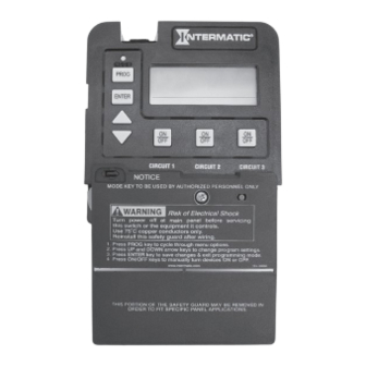
Page 12: An Overview Of The Multipurpose Control Panel
Figure #5 12345... - Page 13 MODE BUTTON With a small tool, press and hold this button down for 5 seconds. Using the Up and Down arrow keys, you can select the appropriate preprogrammed mode that matches your particular pool or spa equipment configuration. Press the ENTER key when finished. PROGRAM BUTTON This button is used to enter programming mode and access different programming features...
- Page 14 Page intentionally left blank...
-
Page 15: Mode Table
IMPORTANT NOTE You should have now completed installing the Intermatic Multipurpose Control and available accessories. Prior to wiring the equipment to the control, you should read and understand Step #6, which clearly defines the individual circuit ratings, available mode settings and their relative wiring diagrams. Below is a quick reference Mode Table. -
Page 16: Step #6 Ratings, Wiring Schematics And Mode Selection
STEP #6 MULTIPURPOSE CONTROL RATINGS, WIRING AND SETTING THE MODE IMPORTANT NOTE There are seven modes to choose from depending on your pool or spa equipment configuration. Each mode has specific programming, timing, and lockout features that are designed to work with specific types of pool or spa equipment. -
Page 17: Mode Descriptions
IMPORTANT NOTE CONCERNING SETTING THE ON/OFF TIMES FOR EACH MODE 1. The “ON/OFF” keys are provided for service operations, and for circumstances where instantaneous response is required. If the intent is to turn equipment on and off everyday at the same time, programming individual events will ensure these functions take place. - Page 18 You would like to run the pump in high speed for EXAMPLE: 6 hours and low speed for the remainder of the time. Program a 6-hour event for high speed, and an 18-hour event for low speed. Do not turn the low speed on manually, and program a 6-hour event for high speed.
-
Page 19: Mode 1 (Aux1, Aux2, Aux3)
3 HP and can handle both 120 VAC and 240 VAC equipment loads. This is the most versatile timer in the market today and can be added to almost all Intermatic control panels, both new and existing, making it ideal for upgrades to older Intermatic systems. -
Page 20: Mode 2 (Pump High, Pump Low, Aux3)
Circuit three is single pole circuit for a generic load, and independent of circuits one and two. Applications: In Mode 2, the P1353ME Three Circuit Clock Mechanism acts as a Two Speed Controller and can be used for two speed pool applications but is ideal for spa applications where the filter pump on the spa is used for filtering in low speed and used for jets in high speed. -
Page 21: Mode 3 (Filter Pump, Aux2, Cleaner Pump)
Circuit two is a single pole circuit for a generic load, independent of circuits one and three. Applications: In Mode 3, the P1353ME Three Circuit Clock Mechanism is ideal for pool applications where a Booster/Cleaner pump is being controlled. -
Page 22: Mode 4 (Pump High, Pump Low, Cleaner Pump)
Applications: In Mode 4, the P1353ME Three Circuit Clock Mechanism acts as a Two Speed Controller and is ideal for pool applications where a booster/cleaner pump is being controlled. -
Page 23: Mode 5 (Pump L1, Pump L2, Aux3)
240 VAC equipment hookup on circuit #1. Even though the P1353ME is not a disconnect, and you can easily control a 240 VAC load by breaking only one leg, some wiring situations may dictate breaking both legs of a 240 VAC load. -
Page 24: Mode 6 (Aux1, Aux2, Aux3)
Applications: In Mode 6, the P1353ME Three Circuit Clock Mechanism is ideal for spa applications where you need to control three pieces of individual equipment (circulation pump, blower, light), but do not want to... -
Page 25: Mode 7 (Pump High, Pump Low, Common)
COMMON Applications: In Mode 7, the P1353ME Three Circuit Clock Mechanism acts as a two speed controller and can be used for two speed pool applications but is ideal for spa applications where the filter pump on the spa is used for filtering in low speed and used for jets in high speed. -
Page 26: Setting The Mode
Setting The Mode 1. With a small blunt instrument, press and hold the Mode Button (Approximately 5 seconds) until the display shows SET MODE and the Mode Number blinks. 2. Use the Up and Down arrow keys to cycle through all available modes. -
Page 27: Step#7 Setting The Time
STEP #7 Setting The Time 1. Press and release the program key. The displayed time will start to blink, and the program menu will display Set Clock. 2. Use the Up and Down arrows to change the time. Take note of the AM and PM indicator when setting time. -
Page 28: Step#8 Setting The On/Off Times
STEP #8 Setting On/Off Times for Each Circuit 1. If you pressed and released the program key from the previous procedure, you should see the following display, if not, press and release the program key twice to get to the following display. - Page 29 3. Once you are satisfied with the start time, press and release the Enter Key. You have now saved the start time, and the display will prompt you for the desired Stop time for circuit #1’s 1st event. 4. Use the Up and Down arrows keys to define the stop time for circuit #1’s 1st event.
-
Page 30: Step#9 Setting The Cool Down Time
STEP #9 Setting The Cool Down Time (Fireman Switch) NOTE The cool down time is a time defined by the programmer. It’s used in conjunction with a pool heater, (See Fig. #1 for heater hookup), and it’s defined as the additional time the pump will run over and beyond the desired pump OFF time with the Fireman switch open. -
Page 31: Step#10 Setting Freeze Protection
Setting Freeze Protection NOTE The freeze protection programming will not appear unless you have installed the Intermatic freeze sensor, (See Fig. #1 for installation and ordering details). Without the freeze sensor installed, programming will end once you have finished programming the cool down cycle, and pressed and released the Program key to advance. -
Page 32: Display Definitions
Display Definitions Cool Down (Fireman Switch) Runtime Display The following example illustrates how the display will look when the cool down feature is activated. In this example, the cool down time was set for 5 minutes, and is in the process of counting down to zero, showing minutes and seconds. -
Page 33: Freeze Control Display
Freeze Control Display The following example illustrates how the display will look when the freeze protection feature is activated. In this example, the freeze sensor was connected, enabling the freeze protection feature. Circuits #1 & #3 were programmed to come on during a freeze condition. Aux #1 &... -
Page 34: Cleaner Pump Display
Cleaner Pump Display The cleaner pump should always be connected to circuit #3 and the mode setting should be set to #3 or #4, depending on the filter pump configuration. Before the cleaner pump can come on, circuit #1 (filter pump) must be on for more than 30 seconds. -
Page 35: Special Features
Special Features Setting The Countdown Timer The countdown timer allows you to turn on a desired load for a pre- defined amount of time without interrupting or setting a new On/Off event. This feature is useful when chemicals are added to the pool or spa water, and the pump needs to circulate the chemicals for a mini- mum amount of time. -
Page 36: Viewing Revision Level
It may be necessary to view the revision level of the internal programming for service purposes, or compatibility issues with future Intermatic Designs. To do so, simply follow the below procedure: 1. Make sure the Multipurpose Control is not in programming mode. -
Page 37: Clearing All On/Off Events
Clearing all scheduled ON/OFF Events Quickly To clear all schedules, follow the procedure below. This function is helpful when you want to start your event programming from scratch and disable all the current ON/OFF events. 1. Press and hold down the PROG key. The display time will blink 2. - Page 38 Notes...
-
Page 39: Warranty
(a) returning the product to the dealer from whom the unit was purchased or (b) completing a warranty claim online at www.intermatic.com. This warranty is made by: Intermatic Incorporated, Customer Service 1950 Innovation Way, Suite 300, Libertyville, IL 60048. For warranty service go to: http://www. - Page 40 158--02086...
Need help?
Do you have a question about the P1353ME and is the answer not in the manual?
Questions and answers
how do i set mode 1 load 1 all circuits to be on all the time
The Intermatic P1353ME does not support keeping all circuits on all the time in Mode 1. Each circuit operates independently, but they follow scheduled ON/OFF events. To keep Load 1 (AUX 1) always on, you can override scheduling by manually turning it on and ensuring no OFF events are programmed for it. However, all circuits being on continuously is not an intended function of the device.
This answer is automatically generated