Table of Contents
Advertisement
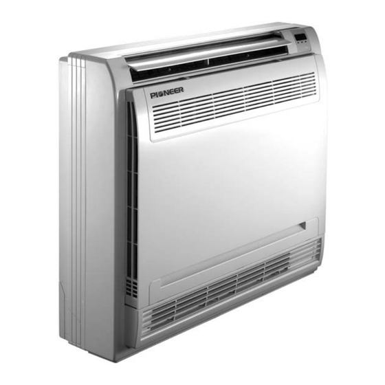
FLOOR CONSOLE MINI SPLIT SYSTEM
AIR CONDITIONER / HEAT PUMP
FAB / FYB Series
FAB: Cooling Only Version
FYB Cooling and Heating Version
Inverter+ and Inverter++ Models
9,000 BTU/h. through 12,000 BTU/h.
Installation
Manual
IMPORTANT NOTICE:
Please read this manual carefully before installing
or operating your new air conditioning system.
Make sure to save this manual for future reference.
Advertisement
Table of Contents

Related Manuals for Pioneer FAB Series


Summary of Contents for Pioneer FAB Series
-
Page 1: Installation Manual
FLOOR CONSOLE MINI SPLIT SYSTEM AIR CONDITIONER / HEAT PUMP FAB / FYB Series FAB: Cooling Only Version FYB Cooling and Heating Version Inverter+ and Inverter++ Models 9,000 BTU/h. through 12,000 BTU/h. Installation Manual IMPORTANT NOTICE: Please read this manual carefully before installing or operating your new air conditioning system. - Page 2 If used as a part of a MULTI Split System, please refer to the Installation & Operation manuals packed with the multi split outdoor unit.
-
Page 3: Table Of Contents
Strictly adhere to these installation instructions. CONTENTS PAGE If installation is done improperly, it may cause water leakage, electrical shock, and possibly fire. PRECAUTIONS......................1 When installing the unit inside a small room, take measures toward keeping refrigerant concentration from INSTALLATION INFORMATION................2 exceeding allowable safety limits, in the event of ACCESSORIES......................3 refrigerant leakage. -
Page 4: Installation Information
If the refrigerant leaks during installation, ventilate the The appliance shall be installed in accordance with area immediately. national wiring regulations. Toxic gas may be produced if the refrigerant comes into contact, whether direct or indirect, with fire. Do not operate your air conditioner in a wet room, such as a bathroom or laundry room. -
Page 5: Accessories
3. ACCESSORIES Please check whether the following list of accessories are of full scope. If there are some spare items, please store them carefully aside. Table 3-1 NAME SHAPE QUANTITY Installation Fittings 1.Hook 2. Remote Controller 3. Frame Remote Controller & Its Frame 4. -
Page 6: Inspecting And Handling The Unit
4. INSPECTING AND HANDLING THE UNIT On delivery, the package should be inspected, and any damage should be reported to the service agent immediately. 700mm 210mm When handling the unit, take into account the following: - Fragile, handle the unit with care. - Keep the unit upright, in order to avoid compressor damage. -
Page 7: Outdoor Unit Installation
6. OUTDOOR UNIT INSTALLATION 6.1 Installation Location The outdoor unit should be installed in a location that meets the following requiements: There is enough spatial clearance for maintenance. The air outlet and the air inlet are not impeded, and cannot be affected by strong winds. The location is dry and well-ventilated. -
Page 8: Install The Connecting Pipe
Side Air Outlet Outdoor Unit 7. INSTALL THE CONNECTING PIPE (Wall or Obstacle) Check to ensure that the height drop between the indoor unit and outdoor unit, the length of refrigerant pipe, and the number of bends meet the following requirements: Air Inlet >30cm Table 7-1... - Page 9 How to Take Indoor Unit Apart to Connect the Pipes Open the Front Panel Slide the two stoppers on the left and right sides inward until they click. (Refer to Fig. 7-1) Fig.7-3 How to take outdoor unit apart to connect the pipes Remove the water tray Remove the water tray...
- Page 10 Connect the indoor unit BEFORE the outdoor unit. EVACUATION OF LINE SET/INDOOR UNIT Important: Ensure the pipe is bent appropriately. Preparations and Precautions Bend the pipe with thumb Air and foreign matter in the refrigerant circuit can cause abnormal rises in pressure, which min-radius 100mm can damage the air conditioner, reduce its Fig.7-6...
- Page 11 Open the BLUE (Low Pressure) valve of the Manifold Evacuation Instructions Gauge. Keep the RED (High Pressure) valve closed. Manifold Gauge Turn the vacuum pump ON to start evacuating the Low Pressure Gauge High Pressure Gauge air from the line set and indoor unit circuits. Run the vacuum pump for at least 15 minutes, or -76cmHg until the Low Pressure Gauge reads -76cmHG...
-
Page 12: Connect The Drain Pipe
8. CONNECT THE DRAIN PIPE Copper Pipe from Indoor Unit Install the Drainpipe of the Indoor Unit Flare Nut The outlet has a PTI screw thread.Please use sealing materials and pipe sheath (fittings) when connecting PVC pipes. CAUTION The drain pipe of the indoor unit must be heat-insulated, or it,as well as the connections of the indoor unit, will condense dew. -
Page 13: Wiring
For power details of the air conditioner, refer to the rating plate on the product. For any other questions, please contact your local dealer. Connect the Cable The base pan hole Seal Drain joint of outdoor unit The installation bearer of the sensing device should be rotated to another side, and then taken off the cover of electrical box. -
Page 14: Test Operation
10. TEST OPERATION Link the connective cables to the terminals, as identified with their respective matching numbers on the terminal block of the indoor and outdoor units. The test operation must be carried out after the entire installation has been completed. Re-install the indoor unit and outdoor unit in their original way. -
Page 15: The Specification Of Power
The Specification of Power Table 9-2 Cooling & Heating Cooling & Heating TYPE 12,000 BTU/hr 16,000-18,000 BTU/hr PHASE 1-PHASE 1-PHASE POWER FREQUENCY & VOLTAGE 208-240V~, 50Hz/60Hz 208-240V~, 50Hz/60Hz CIRCUIT BREAKER/FUSE 20/16 20/16 3x1.0 INDOOR UNIT POWER WIRING GROUND WIRING INDOOR/OUTDOOR OUTDOOR UNIT POWER 3X1.5 3x2.5... - Page 16 Fig.9-5 Power Supply Switch/Fuse (Available locally) Power Wiring (Outdoor) Power Linking Wiring (Indoor) Indoor Outdoor Unit Unit Ground Wiring Strong electric signal link wiring Ground Wiring Weak electric signal link wiring Ground the air conditioner properly to ensure its anti-interference function Fig.10-6 Power Supply Power Supply...
- Page 17 Fig.9-7 Power Supply Switch/Fuse (Available locally) Power Wiring (Outdoor) Indoor Outdoor Unit Unit Ground Wiring Strong electric signal link wiring Ground Wiring Weak electric signal link wiring Ground the air conditioner properly to ensure its anti-interference function CAUTION A disconnection device having an air-gap contact separation in all active conductors should be incorporated in the fixed wiring, according to the National Wiring Regulation.
- Page 18 QS01I-045AW The design and s pecifications are subject to change wi thout prior notic e for product improvement. Cons ult with the s ales agency for manufa cturer for details. is a registered trademark of Parker Davis HVAC International, Inc. Parker Davis HVAC International, Inc.
Need help?
Do you have a question about the FAB Series and is the answer not in the manual?
Questions and answers