Table of Contents
Advertisement
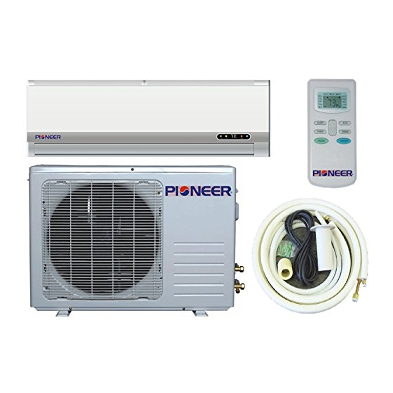
WALL
SPLIT-TYP
WALL MOUNTED SPLIT-TYPEAIR CONDITIONERS
SERVICE MANUAL
Models:
WYD009AL3JAR-L
WYD012AL3JAR-L
WYD018GL3JAR-L
WYD024GL3JAR-L
CONTENTS:
1. IMPORTANT NOTICE···························
2. OPERATION DETAILS··························
3. ELECTRICAL SCHEMATIC DIAGRAM·····
4. EXPLOSION VIEW······························
5. PARTS LIST·······································
MOUNTED
No.TE1307
1
2
11
13
16
Advertisement
Table of Contents


Need help?
Do you have a question about the WYD009AL3JAR-L and is the answer not in the manual?
Questions and answers
I need a new fan for my ac because the blades broke