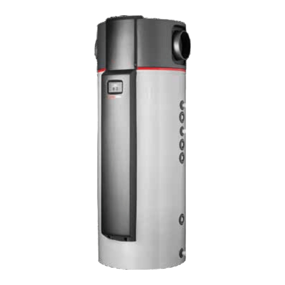
Summary of Contents for Kronoterm WP4 LF-502
-
Page 1: Service Manual
Service manual Heat pump for sanitary water WP4 LF-502 ID.: 17-16-22-2991-03 / 6.2017... - Page 2 This document is copyrighted. Any use outside the provisions of the copyright law without the permission of Kronoterm d.o.o. is illegal and punishable by law. All previous versions of this document are void. We reserve the right to make changes. We reserve the right to change this document and for printing errors.
-
Page 3: Table Of Contents
1. Kazalo Kazalo ........................2 Structure of serial number ..................3 Sestavni deli ......................3 Position of Connections and Dimensions ............5 Removing the front cover ..................6 Removing the housing of the device ..............7 Table of parameters ....................8 Electrical Connection Scheme ................ -
Page 4: Structure Of Serial Number
2. Structure of serial number Example: W XX YY ZZZZ Serial number in current year KRONOTERM Year Calendar week (0001, 0002, 0003, etc.) 3. Sestavni deli ID.: 17-16-22-2991-03 6.2017... - Page 5 Bill of elements WP4 LF-502 Title Ident Seq. No. ISOLATED HOOD 2222000069728 FAN CONDENSER 2222000020804 HOOD COVER 2222000068332 FAN HOLDER 2222000045128 DIFFUSER 2222000049904 EVAPORATOR 2222000045654 ANODE 5/4'' 2222000079765 ELECTROMAGNETIC VALVE WITH A COIL 2222000033583 COMPRESSOR INSULATION 2222000069742 COMPRESSOR 2222000065898 SUPPORTING PANEL, ASSEMBLY...
-
Page 6: Position Of Connections And Dimensions
4. Position of Connections and Dimensions Connection cold water G1'' Connection heat carrier - return G1'' Connection heat carrier - lifting conduit G1'' Circulation connection G3/4'' Hot water connection G1'' Connection for removal of water condensation 16 Connection for additional electric heater 6/4'' ID.: 17-16-22-2991-03 6.2017... -
Page 7: Removing The
5. Removing the front cover Electrical connection of the power cable, additional source, external signal, additional sensor, and additional heater on the front side under the cover. To access the electrical connection, remove the front cover, as shown in the image below: Imbus 4 Figure 1: Removing the front cover ID.: 17-16-22-2991-03... -
Page 8: Removing The Housing Of The Device
6. Removing the housing of the device To access the generator device, it is necessary to remove the housing of the device. Thus, it is necessary to: 1. Unscrew screws on the front and rear cover 2. Remove the front and rear cover (1) 3. -
Page 9: Table Of Parameters
7. Table of parameters Look to Service manual for Controller of heat pump for sanitary water – OPTITRONIC 2, ID:17-16-14-3991-xx. Table of parameters ID.: 17-16-22-2991-03 6.2017... -
Page 10: Electrical Connection Scheme
8. Electrical Connection Scheme Compressor - generator 12 Relay panel 13 Screen Electric heater 14 Electromagnetic valves Safety thermostat 15 Fan connection pins Fan condenser 16 Optical converter Pressure switch 17 High pressure switch relay Temperature feeler NTC - water 18 Additional heater connection pin Temperature feeler NTC - air 19 Power supply connection pins... -
Page 11: Technical Data
8.2.2 10.2.3 24.2 1.1.1 1.2.1 1.2.2 1.1.2 ADD. ~230V SEN. EXT. 3N~400V Figure 3: Electrical connection schematic 9. Technical data Look to Instructions For Use And Installation Heat Pumps for Sanitary Water Heating WP4 LF-502. ID: 10-16-20-2979-xx ID.: 17-16-22-2991-03 6.2017... - Page 12 Company headquarters and production Kronoterm d.o.o. Trnava 5e 3303 Gomilsko Tel.: (00386) 3 703 16 20 | Fax: (00386) 3 703 16 33 | Web-page: www.kronoterm.com E-mail: info@kronoterm.com | Customer support and service.: (00386) 3 703 16 26 | E-mail:...


Need help?
Do you have a question about the WP4 LF-502 and is the answer not in the manual?
Questions and answers