
Subscribe to Our Youtube Channel
Related Manuals for Kronoterm WP4 LF-502


Summary of Contents for Kronoterm WP4 LF-502
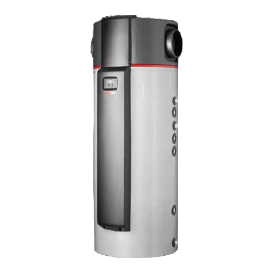
- Page 1 Instructions For Use And Installation Heat Pumps for Sanitary Water Heating WP4 LF-502 This manual is to be handed over to the end user after installation! ID.: 17-16-20-2979-10 / 3.2018...
- Page 2 This document is copyrighted. Any use outside the provisions of the copyright law without the permission of Kronoterm d.o.o. is illegal and punishable by law. All previous versions of this document are void. We reserve the right to make changes. We reserve the right to change this document and for printing errors.
-
Page 3: Table Of Contents
1. Index Index........................3 Important Information ................... 5 Symbols ........................5 General Warnings and Instructions ................. 5 Safety Warnings and Instructions ................6 Obligations of the Manufacturer................9 Obligations of the Installer ..................9 Customer Support - Service ..................9 Obligations of the User .................... - Page 4 7.3.9 Time ........................37 7.3.10 Backup Source .......................37 7.3.11 Overheating Programme - Anti-legionella ...............38 7.3.12 Automatic Quick Water Heating................38 7.3.13 Screen Brightness ....................38 7.3.14 System Information ....................38 7.3.15 Advanced Installation Settings ................39 Device Operation Setting ..................41 Basic Operation ......................41 8.1.1 Basic Operation Programmes ................41 Additional Source ....................42 8.2.1 Correct choice of the additional source ..............42...
-
Page 5: Important Information
2. Important Information The manuals describe the process of installation and maintenance of the device. The installation and maintenance can only be performed by qualified personnel. Read the manual carefully before the installation, this way you will be informed about the intended use, functionality and process of handling the device. -
Page 6: Safety Warnings And Instructions
use are the explicit responsibility of the user alone. NOTE Device installation must be carried out in compliance with instructions or the warranty is null and void. NOTE When designing, projecting, installing and using the device, it is obligatory to take all technical data, warnings and notes from this manual into consideration. - Page 7 WARNING Connection of the device to the power grid must take place in accordance with standards for connection to electrical grids. The device must be connected to the electrical grid via a shutdown element, built into the electrical installation according to valid regulations.
- Page 8 WARNING The device must not be stacked or have items lean against it. If, while the device is operational, the water temperature exceeds 80 °C, contact service. WARNING Ensure, that the device does not represent a danger to anyone. Access to device must be prevented to children and uninstructed persons.
-
Page 9: Obligations Of The Manufacturer
2.4 Obligations of the Manufacturer The manufacturer guarantees that the device is compliant with valid European directives and standards. The device is marked with the CE mark and has all required documentation. We reserve the right to change instructions without previous notifications. The manufacturer accepts no liability in the case of: Failure to follow device installation instructions. -
Page 10: Factory Testing
2.8 Factory Testing To ensure a high quality standard, all heat pumps are tested before leaving the factory in the following aspects: Sealing tightness of the cooling circuit. Watertightness. Airtightness. Electric safety. Functionality. 2.9 Storage The device must be stored in a dry and clean area. Allowed storage temperature is between 10 and 45 °C, short term (up to 24 hours) also up to 55 °C. -
Page 11: Technical Description
3. Technical Description 3.1 General This device is a heat pump for the heating of sanitary water in residential areas and small business premises. When heating sanitary water, the heat pump also cools the area, from which air is captured and / or returned to. The heat pump can thus along with heating of sanitary water, be used for cooling of indoor areas, whereby it has to be emphasized, that the heat pump will only cool the area, if there is a need to heat the sanitary water. - Page 12 The device consists from the device generator (compressor, evaporator, fan, ...) and the hot water tank. The housing of the generator is made of durable plastic and is heat and sound isolated. The device has two attachments for air channels which enable a remote air intake and exhaust from neighbouring rooms or the environment.
-
Page 13: Operation Principle
humidity may be higher. Devices, placed at higher altitudes above sea level may function less efficiently due to lower air pressure. 3.3 Operation Principle 1. Compressor 6. Fan 2. Condenser 7. Magnetic valve 3. Dehydrator 8. Temperature bulb of the expansion valve 4. -
Page 14: Position Of Connections And Dimensions
4. Position of Connections and Dimensions Connection cold water G1'' Connection heat exchanger – return pipe G1'' Connection heat exchanger – supply pipe G1'' Circulation connection G3/4'' Hot water connection G1'' Connection for removal of water condensation 16 Connection for additional electric heater 6/4'' Connection for the installation of a watertight tube with a threaded plug G1/2’’... -
Page 15: Installation
5. Installation The lowest height of ceiling in the room must be 2500. The device is made so that it takes heat from surrounding air or sucks it through air channels and blows it into neighbouring rooms or the environment. The device may be installed in the following ways. Figure 1: Suction and exhaust in the same room (e.g. -
Page 16: Minimal Spacing Of The Device
WARNING The device must not be placed where there are harmful substances, which could damage it, in the air (barns, dangerous substance storage, open air, etc.). 5.1 Minimal spacing of the device: The device may be placed into a room with or without installing air channels. This influences minimal spacing from the walls, which depend on the direction of entry and exit of air. -
Page 17: Device Levelling
Figure 5: Minimal spacing between walls / ceiling in the case of air intake from other rooms or the environment In the case of using air heat from the same room where the device is installed, the room must be at least 50 m 5.2 Device Levelling WARNING The device must be in a vertical position during operation to prevent potential... - Page 18 Should the heat exhanger (heating water) in the water tank not be used for water heating, it must be filled with an anti-freeze liquid, to prevent corrosion in the exchanger. Only close a full exchanger at the bottom (equalisation of pressure due to temperature changes). WARNING Due to use of different materials on the pipe installation, all connections (cold water, hot water, circulation, heat exchanger) on the device must obligatorily be...
-
Page 19: Air Canal Installation
WARNING When installing the device obligatorily place expansion vessel into the system. WARNING Obligatorily install safety valve onto the inflow pipe, which has a nominal pressure of 0,6 MPa (6 bar), and prevents the increase of pressure in the hot water storage for over 0,1 MPa (1 bar) above nominal. -
Page 20: Connection Of Condensation Outlet
Table 2: Accessories Accessories Equivalent length in m Knee 90° (Φ 200 mm) Knee 90° (Φ 250 mm) Reduction piece Φ250 x Φ200 Wall blind 5.5 Connection of Condensation Outlet By removing heat from air, condensation of air moisture also occurs in the heat pump. Depending on air temperature and relative air humidity, the production of moisture from air varies. -
Page 21: Connection Of External Heating Source (Alternative / Additional Source)
Connection of External Heating Source (alternative / additional source) Sanitary water in the water storage tank may be heated with the device generator - heat pump (primary source) and / or additional heat sources (serially equipped electric heater or various external sources). The external source is that which produces heat separately from the device and is connected to the device through a pipe heat exchanger inside the DHW tank. - Page 22 Maximal allowed content of individual substances in heated water and their influence on the heat exchanger are shown in the table below. The heated water which includes any substance in a concentration which causes corrosion (influence "-") in the heating system is forbidden.
- Page 23 Below, there are several possible connection schemes for external sanitary water heating sources. Ball valve Circulation pump (SET SOLAR) Pressure reduction valve Device generator Check valve Furnace Safety valve Heating water hopper Expansion vessel Solar energy collectors Drain tap Differential thermostat Circulation pump External differential thermostat Figure 9: Heat pump combined with furnace.
- Page 24 12.1 12.4 12.3 12.2 Figure 10: Heat pump combined with solar collectors and furnace (SET SOLAR) ID.: 17-16-20-2979-10 3.2018...
-
Page 25: Placement Of External Controller Temperature Probe
5.7 Placement of External Controller Temperature Probe In the case of use an external controller of additional source, attach temperature probe of the external controller into the appropriate canal on the right side of the device, under the black plastic cap (A), as marked on the image. Figure 9: Temperature probe canal on the right side of the device B connection ½'' is intended for installation of the watertight tube of an additional sensor for the measurement of cold water temperature in the device. -
Page 26: Parallel Connection Of Several Devices
5.8 Parallel Connection of Several Devices In case of a need for large quantities of hot water, you can install several devices in a parallel fashion. For appropriate operation, the installation must comply with the instructions below. 5.8.1 Connection of Cold - Hot Water and Circulation Ball valve Circulation pump Reduction valve... -
Page 27: Connection To Boiler
5.8.2 Connection to Boiler Ball valve Release valve Reduction valve Circulation pump Check valve Reduction valve Safety valve Device Expansion vessel Boiler 5.8.3 Air Canal Connection Device Intake canal Exhaust canal Table: Internal diameter of pipes depending on length of canals and number of devices. Number of devices Length canals... -
Page 28: Electric Connection
5.9 Electric Connection Electric connection of the supply cable, external signal, additional temperature probe, and additional heater is done under the cover on the front of the device. To access electrical connections the front cover must be removed as shown below: Figure 10: Front cover removal WARNING Connection of the device to the power grid must take place in accordance with... -
Page 29: Power Supply
Figure 11: Connection pin holder 5.9.1 Power Supply: Power supply is carried out via pins marked with 1. Three connections of power supply are possible: a) Single-phase connection with maximal current load of 16 A is done on pins in the area a, using pins N and L. -
Page 30: Additional Heat Source Connection
b. Single-phase connection with maximal current load of 25 A This connection is used when single-phase power supply with 25 A fuses is available. In this connection type, connect power supply phase to pin 3. This is connected to pin 4 with a bridge (factory connection). -
Page 31: Device Startup
External signal switch is used to switch on various device functions. Connect external switch on positions C1 and C2. WARNING Bring the tension of ~ 230 V on the pins of the external signal and circulation pump. Circulation pump must be connected to the pins under the markings D1, D2 and D3. Connect the steady voltage of ~230 V to D1 and D2 and the neutral lead, and use D3 for the earthing lead. -
Page 32: Controller
7. Controller The interface of device controller OPTITRONIC 2 consists of a colour LCD display and four function keys for operation. back / screensaver increase value forward / confirm / menu decrease value 7.1 Basic Window 7.1.1 Sanitary Water Temperature system statuses LCD screen displays currently measured... -
Page 33: Setting Of Desired Temperature Of Sanitary Water
7.1.3 Setting of Desired Temperature of Sanitary Water In the basic window, by pressing we begin setting the desired temperature of sanitary water. Currently set desired temperature is displayed. By pressing the key the value is increased or decreased. To confirm change of desired sanitary water temperature, press 7.2 Screensavers When we aren't using the controller, the screen displays screensavers. -
Page 34: Menu
Additional screensavers for built in Optitronic WEB module (option): Display of time and date. Time and Display of connection status Display of connection status for date automatically with the cloud (server Water local network connection. synchronised with local time via the Cloud). -
Page 35: Error Acknowledgement
7.3.1 Error Acknowledgement In the case of one or several errors on the device, the menu displays a new setting "Error Acknowledgement". After acknowledging an error the device will restart and check if the cause of error has been removed. If the error has been removed, the setting "Error Acknowledgement"... -
Page 36: Ventilation Schedule
A change of operation programme can be automatic by setting up a daily schedule. Every daily schedule may have two time intervals. Every interval has a set starting time, ending time, and programme of operation. In the time outside the set intervals of the schedule, the device operates according to basic programme. -
Page 37: Vacation
Move between schedule setup windows with the key Turn schedule »ON« or Enter schedule setting Set starting time of Set ending time of schedule »OFF«. with the key schedule interval. interval. NOTE Ventilation according to timetable is blocked when the defrosting function is in progress. (chapter 8.3.6). -
Page 38: Overheating Programme - Anti-Legionella
7.3.11 Overheating Programme - Anti-legionella Programme heats water to 65 °C, to remove potential legionella bacteria. Activation can be automatic or manual. NOTE Factory preset overheating is automatic every 14 days. We advise against overheating too often, as energy consumption during overheating is 1/3 higher than during normal operation. -
Page 39: Advanced Installation Settings
Move between setup windows with the key Enter setting with the key Data about graphic panel Data about main Data about module OPTITRONIC 2. controller Optitronic WEB module OPTITRONIC 2. (option). 7.3.15 Advanced Installation Settings Menu allows access to advanced Use keys controller settings by entering a 4- select number and the key... - Page 40 COMFORT Plus: Switch to programme Backup source: Activation of backup source COMFORT Plus, when power from programme. solar panels is available. Function input 1 Function input 2 Function input 3 7.3.15.4 Standby Setup When water reaches desired temperature, the heating switches off and enters standby mode until water temperature doesn't drop for the standby level difference.
-
Page 41: Device Operation Setting
7.3.15.7 Setting of Temperature of External Source Programme In the case of external source use, maximal temperature is set, up to which the external source may heat water. The standby temperature in this mode is set to a fixed value of 10 °C. Factory temperature setting is 60°C. -
Page 42: Additional Source
8.2 Additional Source For the functioning of the backup source, the following must be done correctly: Choosing the type of backup source, Choosing the operation mode of the external source, Making an electrical connection between the external source and ... -
Page 43: Additional Operation Programmes
least 5 °C higher than the temperature of the buffer tank for DHW, the external source is available and is used for heating water. When n-minutes elapse after turning on the external source and its temperature is not higher than 5 °C, the electrical signal for turning on the external source turns off for 3 x n-minutes;... -
Page 44: Anti-Freeze Programme
Water is heated only by generator of the device. The temperature to which the water is being heated by the programme of quick heating depends on the programme in which the device operates: Basic operation programmes: Water is heated to temperature, defined by programme COMFORT. -
Page 45: Errors And Warnings
During the "Defrosting" programme, the display shows the defrosting icon 9. Errors and Warnings 9.1 Warnings Warnings on the screen of the controller are shown with a yellow triangle and codes W01-W07. Codes have following meanings: WARNING W01 - Entry Air Temperature Too Low If the entry air temperature drops under minimal air temperature (-7°C), the generator of the device is shuts down. -
Page 46: Errors
To remove error, check fan speed (chapter 7.3.15.8) or ensure higher entering air temperature. Should warmer air not be available, it is recommended to manually activate the backup source (chapter 7.3.10), or additional source (chapter 7.3.3), if one is selected (chapter 7.3.15.2). - Page 47 appears, the device shuts down and Anti-Freeze program becomes active (chapter 8.3.3). Service has to be called to remove the error. Error E05 – High Pressure Error Should within 1 hour pressure in the cooling system of the generator be detected as too high thrice (WARNING W03), the device shuts down and Anti-Freeze program becomes active (chapter 8.3.3).
-
Page 48: Errors Of The Optitronic 2 - Web Module (Option)
Error E07 – External Source Temperature Difference Error In the case that the system is connected to an external source which the device may activate via electric signal (oil / gas / pellet / wood furnace, external electric heater), the controller checks the temperature of the external source after activation. -
Page 49: Removal And Disposal
10. Removal and Disposal The device as a whole, when complying with the instructions for safe use and maintenance, has a set operational time of at least 8 years. Individual components have different operational times, thus, upon potential defects and mechanical damage, they need to be replaced with new ones. -
Page 50: Electrical Connection Scheme
13. Electrical Connection Scheme Compressor - generator 12 Relay panel 13 Display Electric heater 14 Electromagnetic valves Safety thermostat 15 Fan connection pins Fan capacitor 16 Optical converter Pressure switch 17 High pressure switch relay Temperature probe NTC - water 18 Additional heater connection pin Temperature probe NTC - air 19 Power supply connection pins... -
Page 51: Technical Data
14. Technical data DEVICE WP4 LF-502 VERSION -Heat source Internal | external air -Controller Optitronic 2 -Thawing Active - hot gas circuit -Electric heater 2 x 2000 EFFICIENCY -CONDITION A20W10-55 -Nominal heating power 7830 (3830 + 2 x 2000) -Device generator heating power... -
Page 52: Legend Of Data Label
15. Legend of data label Characteristics Mark Maximal compressor electrical power. Maximal electrical heater power. Maximal additional load electrical power (circulation pump, etc.). Maximal electrical power of the device (compressor + electric heater + additional load). Cooling circuit. DHW. Heat exchanger in the DHW. Heating system. - Page 53 ID.: 17-16-20-2979-10 3.2018...
- Page 54 ID.: 17-16-20-2979-10 3.2018...
- Page 55 ID.: 17-16-20-2979-10 3.2018...
- Page 56 Company headquarters and production Kronoterm d.o.o. Trnava 5e 3303 Gomilsko Tel.: (00386) 3 703 16 20 | Fax: (00386) 3 703 16 33 | Web-page: www.kronoterm.com E-mail: info@kronoterm.com | Customer support and service.: (00386) 3 703 16 26 | E-mail:...
Need help?
Do you have a question about the WP4 LF-502 and is the answer not in the manual?
Questions and answers