Table of Contents
Advertisement
Advertisement
Table of Contents

Related Manuals for Sper scientific 860032


Summary of Contents for Sper scientific 860032
- Page 1 Bench-Top Meters 860031, 860032 and 860033 Instruction Manual...
-
Page 2: Table Of Contents
TABLE OF CONTENTS INTRODUCTION ..................4 FEATURES .....................4 POWER SUPPLY ...................5 METER COMPONENTS ................5 LCD DISPLAY ..................8 KEYPAD ....................9 REAR PANEL ..................10 SETUP MODE .................11-22 Memory Transmission ...............11 Clear Memory ..................12 View Slope & Offset (pH Probe) ............13 Calibration Review (Conductivity Probe) ...........15 pH Calibration Buffer (pH Probe) ............16 Select Buffer ..................16 Cell Constant (Conductivity Probe) ...........17... - Page 3 MEASUREMENT PROCEDURES ..........29-38 Preparing for Measurement ..............29 Hold Function ..................29 pH Measurement ................30 mV Measurement (± 499 mV) ............31 ORP (mV) Measurement (± 1999 mV) ..........32 Conductivity Measurement ..............32 Total Dissolved Solid Measurement ..........33 Salinity Measurement ................34 Automatic Temperature Compensation ..........35 Manual Temperature Compensation ..........35 Auto and Manual Range ..............36 Record Memory .................37...
-
Page 4: Introduction
Sper Scientific. INTRODUCTION Sper Scientific is pleased to offer the following line of bench-top meters: Model 860031 (pH/mV) Model 860032 (Conductivity/TDS/Salinity) Model 860033 (Water Quality) Please note that the meter itself is identical in each of the above models. -
Page 5: Power Supply
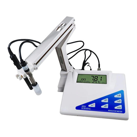
POWER SUPPLY The meter is powered by a 9 Volt DC adapter (included). The plug of the adaptor is USA type; you will need to purchase a plug converter if using the meter outside of the US. Plug the adaptor into the power port labeled “DC,” located on the rear of the meter. - Page 6 METER COMPONENTS Probe Holder The probe holder is composed of two parts: the base and arm. Holder assembly does not require tools. The maximum swing angle is 70° and the maximum height of the holder is 378 mm. Holder Assembly Holder Disassembly To disassemble the holder from the base: 1.
- Page 7 METER COMPONENTS Attaching Holder to the Meter After assembling the holder, attach the holder to the meter. 1. Find the two holes on the bottom of the meter that are used to hold the base. 2. The holder can be attached to the right or left side of the meter Locate the two holes at the bottom of the meter.
-
Page 8: Lcd Display
LCD DISPLAY Primary Data Screen displays pH, mV, ORP, Conductivity, TDS or Salinity value. Icons CON, TDS, SALT, ORP, pH, mV indicate the parameter displayed. Icons ppt, ppm, mg/l, mS, µS, kPA, or mmHg indicate the unit of measure displayed. READY indicates the reading is stable. -
Page 9: Keypad
KEYPAD POWER/SET Press to turn the meter on/off. Press and hold for more than 1 second to enter SET Mode. The meter will default to the last mode used when turned off and back on. CAL/ESC Switch between NORMAL and CALIBRATION Mode. -
Page 10: Rear Panel
REAR PANEL The bench-top meter provides a complete set of input connectors for various commonly-used accessories: Connection Function Connection of the AC to DC adaptor power supply RS232 Connection of a RS232 or USB cable to a computer to capture online or stored data Conductivity probe input GND (I) Earth ground jack inputs (standard tip connectors) -
Page 11: Setup Mode
SETUP MODE The advanced Setup Mode allows you to customize the following meter preferences and defaults: • Memory Transmission • Clear Memory • Slope and Offset (pH) or Calibration Review (Conductivity) • Buffer Solution (pH) or Cell Constant (Conductivity) • Temperature Setting (pH) •... -
Page 12: Clear Memory
SETUP MODE 3. Press . “OUT” flashes on the upper display and P1.1 appears under “OUT.” This indicates that memories are transferring. After transmission, the LCD will return to P1.0. Note.. The meter can store up to 99 records for each parameter. If you want to transmit data for a different parameter, press MODE to select your parameter before entering setup. -
Page 13: View Slope & Offset (Ph Probe)
SETUP MODE 5. Press ▲ to change the status from “NO” on the display to “YES” and then press again to confirm clear memory. The LCD will return to P2.0 when all memories are deleted. CAUTION: THE MEMORY CLEAR PROGRAM IS DESIGNED TO CLEAR 99 MEMORIES AT ONE TIME. - Page 14 SETUP MODE 4. Press to enter P3.1, the LCD displays one of four available slope values; P3.1, P3.2, P3.3, P3.4. If the value is less than 75% or more than 115%, change the probe immediately. 5. Press to enter P3.2, P3.3, and P3.4. Note...
-
Page 15: Calibration Review (Conductivity Probe)
SETUP MODE Calibration Review (Conductivity Probe) This feature allows you to review which range has been calibrated and the last calibration value. The program reviews the probe calibration data of Conductivity, TDS or SALT. Note… If the range is not yet calibrated, the LCD will display the default value. There are 5 total calibration ranges for Conductivity, TDS and SALT. -
Page 16: Ph Calibration Buffer (Ph Probe)
SETUP MODE pH Calibration Buffer (pH Probe) This meter allows the selection of two different types of pH buffers: NIST or CUSTOM. Selection of the proper buffer more accurately calibrates the probe to specific requirements. NIST buffer: List of N.I.S.T. buffer recognition points. pH 1.68, 4.01, 6.86, 9.18, 12.45 CUSTOM buffer: pH 1.00 to 3.00, 3.50 to 5.50, 6.00 to 8.00, 8.50 to 10.50, 11.50 to 13.50... -
Page 17: Cell Constant (Conductivity Probe)
SETUP MODE 5. Press to confirm and the meter will return to P4.0. 6. Press ESC to return to Normal Mode. Cell Constant (Conductivity Probe) To view the probe data (cell constant) of each range: Note… If the range is not yet calibrated, the LCD will display the default value (1.000). 1. -
Page 18: Temperature Setting (Conductivity Probe)
SETUP MODE Temperature Setting (Conductivity Probe) Use this program to set the temperature parameters and TDS conversion factors. 1. Press MODE to select the probe program. 2. Press SET for 2 seconds to enter setup. 3. Press ▲ to select COEF. “COEF” will appear on the middle of the LCD and P5.0 will appear on the lower portion. - Page 19 SETUP MODE Note… When using Manual Temperature Compensation Mode (MTC), you must set the temperature solution in P5.3. 7. At P5.1, press twice to enter P5.3. The default “25.0” flashes on the middle of the LCD and P5.3 will appear on the lower portion. To adjust the solution temperature setting, press ▲...
-
Page 20: Ready Icon
SETUP MODE Ready Icon This feature enables/disables the “READY” icon, which indicates that the measured reading is stable. 1. Press SET for 2 seconds to enter setup. 2. Press ▲ to select “READY” on the display. P6.0 will appear on the lower display. -
Page 21: Real Time Clock Setting
SETUP MODE 3. Press to enter P7.1. The last selected unit “C” or “F” will appear on the LCD. 4. Press ▲ to select either display. 5. Press to save the selection and return to P7.0. 6. Press ESC to return to Normal Mode. Real Time Clock Setting This procedure adjusts the meter’s internal clock. -
Page 22: Reset
SETUP MODE 5. Press ▲ and ▼ to adjust values up or down, respectively. 6. Press ESC to return to P8.0. 7. Press ESC to return to Normal Mode. Reset This procedure will reset the meter to factory default settings. Memory locations are not reset after this procedure. -
Page 23: Ph Probe Calibration
PH PROBE CALIBRATION Calibration is necessary before measurement. Make certain that the buffer value is close to that of the sample being measured and that the buffer temperature remains stable. 1. Press POWER to turn the meter on and press MODE continuously to select pH. - Page 24 Note... If this secondary value continues to fluctuate, check the buffer or probe. (Refer to TROUBLESHOOTING page 42). If CUST is selected, the lower middle display indicates the default, 2.00. Press HLD to select the buffer range needed. Press ▲ or ▼ to adjust the lower middle display to coincide with the main display reading.
-
Page 25: Conductivity Probe Calibration
CONDUCTIVITY PROBE CALIBRATION Selecting Calibration Standard Solution For best results, select a conductivity, TDS or NaCl standard near the sample value that you are measuring. Alternatively, use a calibration solution value that is approximately 2/3 of the full scale of the measurement range that you plan to utilize. - Page 26 CONDUCTIVITY PROBE CALIBRATION Selecting Calibration Schedule For first use and best results, use solution to calibrate. If the conductivity of the measured solution is < 100 µS or the TDS is < 50 ppm, calibrate the meter weekly to achieve the specified accuracy. If the meter is used in the mid ranges, calibrate the unit monthly.
- Page 27 CONDUCTIVITY PROBE CALIBRATION 9. Press ▲ or ▼ to adjust the value on the primary display to match the value of the standard buffer. There are two options: • To input the value based on current temperature, the Temperature Coefficient (page 18) must be 0.0. •...
-
Page 28: Tds Calibration
TDS CALIBRATION There are two options for TDS calibration: Option 1: Using TDS Standards The procedure for TDS calibration is almost the same as the procedure for conductivity calibration. Differences are as follows: 1. Select the TDS standard for calibration. The default TDS conversion factor is 0.50. -
Page 29: Measurement Procedures
MEASUREMENT PROCEDURES Preparing for Measurement 1. Assemble the probe holder and attach the holder to the meter (pages 6-7). 2. Connect an adaptor to the power jack. Slide the adaptor jack into the meter, making sure it is firmly in place. (The meter’s voltage is 9V.) 3. -
Page 30: Ph Measurement
MEASUREMENT PROCEDURES pH Measurement pH measurement range is 0 to 14 pH. This meter is designed to take readings with automatic or manual temperature compensation. Automatic temperature compensation only occurs when a temperature sensor is plugged into the meter. For manual temperature compensation, the default setting is 25°C. -
Page 31: Mv Measurement (± 499 Mv)
MEASUREMENT PROCEDURES mV Measurement (± 499 mV) mV measurement range is from -499 mV to +499 mV with a pH probe. 1. Follow Step 1 in the pH Measurement section (page 30) to clean and soak the probe. 2. Press POWER to turn the meter on. Press MODE to select mV mode. 3. -
Page 32: Conductivity Measurement
MEASUREMENT PROCEDURES Conductivity Measurement The conductivity probe measures 0 to 19.99 uS/cm, 0 to 199.9 uS/cm, 0 to 1999 uS/cm, 0 to 19.99 mS/cm, 0 to 199.9 mS/cm. In Normal Mode, the ATC indicator appears in the lower right corner of the LCD to indicate Automatic Temperature Compensation. -
Page 33: Total Dissolved Solid Measurement
MEASUREMENT PROCEDURES Total Dissolved Solid Measurement TDS readings display ppm or ppt on the LCD. The ATC indicator appears in the lower right corner of the LCD to indicate Automatic Temperature Compensation. If you select MTC, the ATC indicator will disappear. When selecting MTC, you must first deactivate ATC in P5.1 (page 18) and then set a MTC value in P5.3 (page 18). -
Page 34: Salinity Measurement
MEASUREMENT PROCEDURES Salinity Measurement Use a conductivity probe to measure salinity range: 0 to 80 ppt (NaCl) with temperature compensations and temperature coefficient settings. Before measuring, remove the probe cover if needed. To measure: 1. Rinse the probe with de-ionized or distilled water. 2. -
Page 35: Automatic Temperature Compensation
MEASUREMENT PROCEDURES Automatic Temperature Compensation pH Probe Plug the temperature connector sensor into the ATC port at the rear of the meter. Conductivity Probe The temperature sensor is built into the conductivity probe. Plug the probe only into the MIC port at the rear of the meter. Manual Temperature Compensation pH Probe 1. -
Page 36: Auto And Manual Range
MEASUREMENT PROCEDURES Auto and Manual Range Press while in Normal Mode to select automatic or manual range function. Mode SALT Auto Full range Full range Full range Range 1 0 to 19.99 uS 0 to 19.99*f ppm Range 2 0 to 199.9 uS 0 to 199.9*f ppm Range 3 0 to 1999 uS... -
Page 37: Record Memory
MEASUREMENT PROCEDURES 3. When in manual range mode, E03 will appear on the LCD when the measured value is out of range. Select another range. 4. The meter will return to auto range when it is turned off. Record Memory The meter can store up to 99 records each of pH, mV, and ORP (mV), conductivity, TDS and salinity readings. -
Page 38: Recall Maximum & Minimum
MEASUREMENT PROCEDURES 2. Press ▲ to select the next memory content. Press ▼ to select the previous memory. 3. Press REC for more than 2 seconds to exit memory recall and return to Normal Mode. Note… All records are retained even when the meter is off. To clear records, see page 12. -
Page 39: Maintenance
MAINTENANCE pH Probe It is important to keep the pH probe wet when not in use. The probe is protected by a plastic bottle containing solution. To use or store the probe: 1. Rotate the bottle to remove the bottle from the probe. Pull down the cover and remove it from the probe. - Page 40 MAINTENANCE The following actions will keep the probe in good working condition: • Always keep the pH glass bulb wet by using the plastic bottle containing the KCI solution to protect and store the probe. Never use distilled or de-ionized water for storage (only to rinse). •...
- Page 41 MAINTENANCE Probe Testing 1. Connect the ORP probe to the meter via the BNC connector. 2. Put the probe in a buffer solution of pH 7.00 with saturated quinhydrone. 3. Stir; mV reading (E1) should be 86 ±15 mV. 4. Rinse the probe with distilled water, then set the probe in pH 4.01 buffer solution with saturated quinhydrone.
-
Page 42: Troubleshooting
3. Check to see if the meter is in “MTC,” if so, input the temperature value. Slow response: 1. Clean and re-calibrate or replace the probe. Wrong real time: Incorrect real time display will not affect the measurements. The internal battery needs replacing. Contact Sper Scientific for battery replacement procedures. -
Page 43: Error Codes
ERROR CODES Reading is under the lower range limit; See page 52 for range specifications for all parameters Reading is over the upper range limit; See page 52 for range specifications for all parameters Error in measuring original data (damaged temperature sensor or temperature out of specifications) results in conductivity or pH value error. -
Page 44: Pc Connection
PC CONNECTION The meter can interface with a personal computer to capture on-line or stored data. Connection procedures: 1. Plug a USB or RS232 cable into the jack labeled RS232 on the rear side of the meter. 2. Plug the USB connector into a computer. COM ports 1-8 can be used. 3. - Page 45 Protocol Information RS232 protocol settings: 9600 bps, 8 data bits, no parity. (Transmits ASCII code every second.) Normal Data: pxx.xxpH: mxx.xxmV: Cxxxx(xx.xx, xxx.x)mS(uS) : Dxxxx(xx.xx, xxx.x) ppm(ppt) : Sxx.xxppt:Txxx.xC(F):Txxx.xC(F) @ 2007-04-18 18:48:48LRCCRLF Errors: ExxNul: ExxNul: ExxNul: ExxNul: ExxNul: ExxNull: ExxNul @ 2007-04-18 18:48:48LRCCRLF Description:...
- Page 46 Format in Memory Transmit (Conductivity Mode) Normal Data: Cxxxx(xx.xx, xxx.x)mS(uS) : Txxx.xC(F) #xx @2007-04-18 18:48:48LRCCRLF Errors: ExxNul: ExxNul #xx @2007-04-18 18:48:48LRCCRLF Description: $Cond: Temp LRC CRLFPC CONNECTION Format in Memory Transmit (TDS Mode) Normal Data: Dxxxx(xx.xx, xxx.x)ppm(ppt) : Txxx.xC(F) #xx @2007-04-18 18:48:48LRCCRLF Errors: ExxNul: ExxNul #xx @2007-04-18...
-
Page 47: Appendices
APPENDICES APPENDIX A: CONDUCTIVITY to TDS CONVERSION FACTORS Conductivity TDS KCl TDS NaCl TDS 442 at 25°C Factor Factor Factor value value value 1413 uS 744.7 0.527 702.1 0.4969 1000 0.7078 2070 uS 1045 0.5048 1041 0.5029 1500 0.7246 2764 uS 1382 1414.8 0.5119... - Page 48 APPENDICES APPENDIX C: TEMPERATURE EFFECT Conductivity measurements are temperature dependent; if the temperature increases, conductivity increases. For example, the conductivity measured in a 0.01 M KCl solution at 20°C is 1.273 mS/cm, whereas at 25°C, it is 1.409 mS/cm. The concept of reference temperature (Normalization temperature) was introduced to allow the comparison of conductivity results obtained at different temperatures.
- Page 49 APPENDICES Calculating Temperature Coefficients (θ) By measuring the conductivity of a sample at temperature T1 close to Tref and another temperature T2, you can calculate the temperature coefficient by using the following equation: T2 should be selected as a typical sample temperature and should be approximately 10°C different from T1.
- Page 50 APPENDICES APPENDIX D: TEMPERATURE EFFECT ON NIST pH BUFFERS 0°C 5°C 10°C 15°C 20°C 25°C pH 1.68 1.67 1.67 1.67 1.67 1.68 1.68 pH 4.01 4.01 4.01 4.00 4.00 4.00 4.01 pH 6.86 6.98 6.95 6.92 6.90 6.88 6.86 pH 9.18 9.47 9.38 9.32...
-
Page 51: Optional Accessories
3 bottles, 40mL each 860010 pH10, 3 bottles, 40mL each 860011 De-ionized Water, 3 bottles, 40mL each 860030H Bench Top Probe Holder Arm For 860032 (Conductivity/TDS/Salinity) 850038P Replacement Conductivity/TDS/Salinity Probe 840054 USB Cable 860030H Bench Top Probe Holder Arm... -
Page 52: Specifications
SPECIFICATIONS Unit of Range Resolution Accuracy Measure 0 to 14 pH 0.01 pH ± 0.02 pH -1999 to 1999 mV 0.1 mV (-199.9 to ± 0.2 mV (-199.9 199.9 mV) to 199.9 mv) otherwise 1 mV otherwise ± 2 mV Conductivity 0 to 19.99 uS 0.01 uS ±... - Page 53 SPECIFICATIONS pH Slope/Offset display (pH Mode only) Slope alarm Out of 75% to 115% (pH) Offset alarm Out of ±60 mV (pH) Conductivity cell constant 1.0 (Conductivity) Conductivity Temperature 0.0% to 10.0%/°C (Conductivity) Coefficient (Tc) Reference temperature Factory set at 25°C (Tref) (Conductivity) TDS conversion factor...
- Page 54 SPECIFICATIONS Conductivity Default Settings Program Function Default Display Note P1.0 Memory transmitting No default “tr” Follow Cond P1.1 MEM sent by “out” or TDS of RS232 Normal Mode P2.0 MEM clear “CLr” Follow Cond P2.1 CLR confirm “no” or or TDS of Always “yes”...
- Page 55 SPECIFICATIONS pH/mV Default Settings Program Function Default Display Note P1.0 Memory transmitting “tr” Follow pH P1.1 MEM sent by “out” or mV of No default RS232 Normal Mode P2.0 MEM clear “CLr” Follow pH P2.1 CLR confirm “no” or or mV of Always “yes”...
-
Page 56: Warranty
WARRANTY Sper Scientific warrants this product against defects in materials and workmanship for a period of five (5) years from the date of purchase, and agrees to repair or replace any defective unit without charge. If your model has since been discontinued, an equivalent Sper Scientific product will be substituted if available.
Need help?
Do you have a question about the 860032 and is the answer not in the manual?
Questions and answers