Table of Contents
Advertisement
Quick Links
Advertisement
Table of Contents

Related Manuals for Sper scientific 850081DOK


Summary of Contents for Sper scientific 850081DOK
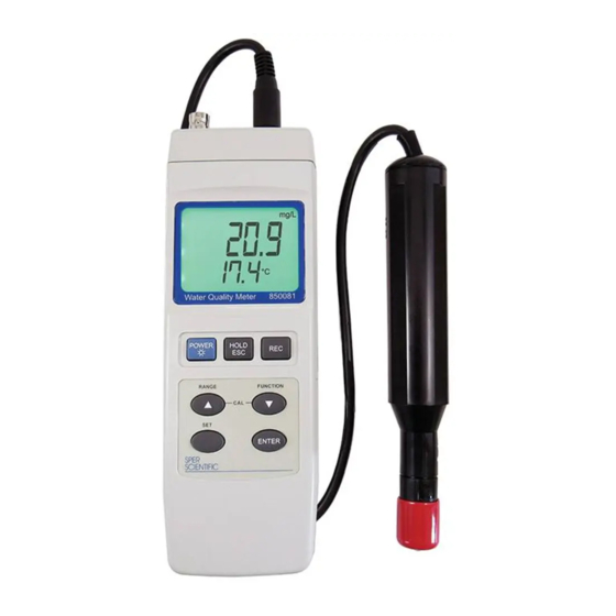
- Page 1 Dissolved Oxygen Meter Kit 850081DOK Instruction Manual...
- Page 2 Dissolved Oxygen Meter Kit - 850081DOK Copyright ©2017 by Sper Scientific ALL RIGHTS RESERVED Printed in the USA The contents of this manual may not be reproduced or transmitted in any form or by any means electronic, mechanical, or other means that do not yet exist or may...
-
Page 3: Table Of Contents
TABLE OF CONTENTS INTRODUCTION ....... . 4 FEATURES........5 MATERIALS SUPPLIED . -
Page 4: Introduction
INTRODUCTION This Sper Scientific Dissolved Oxygen Meter Kit (Model 850081DOK) comes with dissolved oxygen (DO) probe (850081DO) and also uses optional, interchangeable probes to read pH, millivolt (mV)/ oxygen reduction potential (ORP), conductivity, total dissolved solids (TDS), salinity, and temperature. Order only the probes required for your current parameters and add additional probes in the future. -
Page 5: Features
FEATURES • Reads DO, and has the option to read pH, mV/ORP, conductivity, TDS, salinity and temperature with optional probes • Automatic temperature compensation • Salinity and altitude compensation for DO measurements • Maximum and minimum values • Hold function •... -
Page 6: Front Panel Description
FRONT PANEL DESCRIPTION 1. LCD Display 11. Battery Compartment Cover Screw 2. Power/Backlight Button 12. Tripod Mounting Screw 3. Hold/Escape Button 13. Temperature Probe 4. Record Button Socket 5. ▲/Range Button 14. Dissolved Oxygen 6. ▼/Function Button Probe Socket 7. Set Button 15. -
Page 7: Setup
SETUP Meter On and Off 1. Press POWER to turn the meter on. 2. Press and hold POWER for 3 seconds and release to turn the meter off. Backlight The backlight will illuminate automatically when the meter is turned on. 1. - Page 8 Beeper 1. In Setup Mode, press SET until “bEEP” is displayed. 2. Press ▲ or ▼ to toggle between “Yes” (beeper is on) or “No” (disable beeper). 3. Press ENTER to save the selection. 4. Press SET to continue to the next setup parameter, or press ESC to exit Setup Mode.
- Page 9 Select DO Altitude Compensation in Meters This feature is active in DO Mode only. 1. In Setup Mode, press SET until “HIGh” is displayed. 2. The default value is 0 meters. Press ▲ or ▼ to adjust the upper altitude compensation value in increments of 100 meters.
-
Page 10: Measurment Functions
Select pH Manual Temperature Compensation Value This feature is active in pH Mode only. 1. In Setup Mode, press SET until “t-SEt” is displayed. 2. The default value is 25° C / 77° F. Press ▲ or ▼ to adjust temperature compensation value. - Page 11 3. Follow the specific measurement procedures for the parameter in use. Parameter Page mV (ORP) Conductivity Salinity Data Hold Function 1. During measurement, press HOLD to freeze the reading on the display. “Hold” appears on the LCD. 2. Press HOLD to return to Normal Mode. Minimum and Maximum Values 1.
-
Page 12: Ph Measurements
pH MEASUREMENT (for use with 840016, 840049 & 840051 optional probes) Calibration The pH probe should be calibrated before first use. Recalibrate regularly to ensure highly accurate measurement. Note… Calibration should begin with pH 7.00 and then be followed by either pH 4.00 or pH 10.00. Be sure to rinse the electrode in distilled water between calibration points. - Page 13 11. To clear the existing calibration data, select “CLr” from the calibration options. 12. Press ENTER to confirm the selection and return to Normal Mode. pH Probe Calibration with Manual Temperature Compensation 1. Plug and secure the pH probe into the pH socket on top of the meter.
- Page 14 2. Plug the temperature probe into the TEMP socket on top of the meter. 3. Press POWER to turn the meter on. 4. Press FUNCTION to cycle through the available functions until “pH” is displayed. 5. Immerse the temperature probe into the solution to be measured.
-
Page 15: Do Measurements
2. Press POWER to turn the meter on. 3. Press FUNCTION to cycle through the available functions until “OrP” is displayed. 4. Hold the electrode handle and immerse the sensing head completely into the solution to be measured. 5. Gently shake the electrode. 6. - Page 16 6. Press ENTER. The display will count down from 30 to 0 as calibration occurs. 7. The meter returns to Normal Mode. Do Measurement 1. Plug the DO probe (850081DO) into the DO socket on top of the meter. 2. Press POWER to turn the meter on. 3.
-
Page 17: Conductivity Measurements
CONDUCTIVITY MEASUREMENT (for use with 850081C/TD or 850081C/SG optional probes) Conductivity Probe Calibration The conductivity probe should be calibrated before first use. Recalibrate the probe periodically to ensure accuracy. Note… One-point calibration should be executed at 1.413 mS. For multi-point calibration, execute 1.413 first and then proceed to other ranges. - Page 18 Conductivity Measurement 1. Plug the conductivity probe into the CD socket on top of the meter. 2. Press POWER to turn the meter on. 3. Press FUNCTION to cycle through the available functions until “Cd” is displayed. 4. Hold the electrode handle and immerse the sensing head completely into the solution to be measured.
- Page 19 TDS Measurement 1. Plug the conductivity probe into the CD socket on top of the meter. 2. Press POWER to turn the meter on. 3. Press FUNCTION to cycle through the available functions until “tdS” is displayed. 4. Hold the electrode handle and immerse the sensing head completely into the solution to be measured.
-
Page 20: Specifications
POWER SUPPLY Battery Power This meter uses one DC 9 V (006 P) heavy-duty alkaline battery. To install the battery before first use: 1. Unscrew and remove the screw on the back battery cover. 2. Slide off the battery cover in the direction of the arrows. 3. - Page 21 General Specifications Circuit Custom one-chip microprocessor LSI circuit Display 52 x 38 mm LCD Sample Rate ~ 1 second Data Output RS 232 / USB PC computer interface Operating < 85% RH Operating 0 - 50 °C Temperature 32 - 122 °F Power ~ DC 14 mA with backlight off Consumption...
-
Page 22: Probes
Temperature Automatic (ATC) from 0 to 60 °C (32 to Compensation 140 °F) with temperature compensation factor variable between 0 to 5.0% per °C. Probe 0 to 60 °C Operating Temperature Conductivity Measurement Range Accuracy 0 - 200.00 uS 200 uS 0.1 uS ±... -
Page 23: Accessories
Temperature Automatic (ATC) from 0 - 50 °C Compensation Salinity 0 - 50% salt Compensation Altitude 0 - 8900 meters Compensation (M.T.) Measurement Range Accuracy Dissolved 0 - 20.0 mg/L 0.1 mg/L ± 0.4 mg/L Oxygen Oxygen in Air 0 - 100.0% 0.1% O2 ±... -
Page 24: Warranty
WARRANTY Sper Scientific warrants this product against defects in materials and workmanship for a period of five (5) years from the date of purchase, and agrees to repair or replace any defective unit without charge. If your model has since been discontinued, an equivalent Sper Scientific product will be substituted if available.
Need help?
Do you have a question about the 850081DOK and is the answer not in the manual?
Questions and answers