Table of Contents
Advertisement
Quick Links
Advertisement
Table of Contents

Subscribe to Our Youtube Channel
Related Manuals for Sper scientific 800050


Summary of Contents for Sper scientific 800050
- Page 1 Datalogging IAQ Meter 800050 Instruction Manual...
- Page 2 Datalogging IAQ Meter 800050 Copyright ©2014 by Sper Scientific ALL RIGHTS RESERVED Printed in the USA The contents of this manual may not be reproduced or transmitted in any form or by any means electronic, mechanical, or other means that do not yet exist or may...
-
Page 3: Table Of Contents
TABLE OF CONTENTS 1. INTRODUCTION ....5 2. FEATURES ....6 3. -
Page 5: Introduction
INTRODUCTION This Sper Scientific Datalogging IAQ Meter 800050 is ideal for measuring indoor air quality in crowded public spaces with potentially high levels of CO2 (carbon dioxide) such as offices, factories, classrooms, hospitals and hotels. Recalls the maximum and minimum CO2 readings and has a user selectable audible maximum alarm. -
Page 6: Features
FEATURES • Measures Air Temperature, RH, CO2, Dew Point and Wet Bulb • Recalls the min/max CO2 readings. • User selectable audible maximum alarm. • Calibrates to air • Hold function • Records up to 32,000 data points of temperature, RH, and CO2 •... -
Page 7: Meter Components
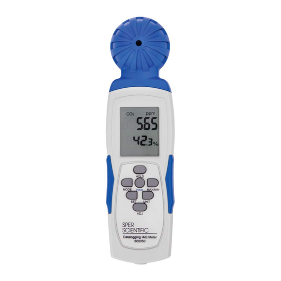
METER COMPONENTS 1. Sensor 2. LCD Display 3. Hold Button 4. Mode Button 5. Power Button 6. Max/Min Button 7. Set Button 8. Unit Button 9. Adjust Button/Key Start 10. Battery Compartment (on back, not pictured) 11. USB Driver/Datalogging Software CD... -
Page 8: Abc & Manual Calibration
ABC CALIBRATION Connect the AC Power supply to the meter. The meter defaults to automatic baseline calibration (ABC) when the unit is turned on. ABC ensures accuracy by eliminating the zero drift of the infrared sensor. This will automatically calibrate the meter at the minimum CO2 reading detected during 15 days of continuous metering. -
Page 9: Measurement Procedures
seconds. “CAL” will appear on the LCD. 3. The meter will display a countdown from 60, as it needs 60 seconds to calibrate, as well as “400” in the middle of the screen. 4. Once completed, the meter will reset and the current readings will now display. -
Page 10: Hold Function
Note… When CO2 exceeds 1000 ppm, both the alarm (bell) icon and the red LED will flash a warning. When the CO2 level falls below this threshold, these visual alarms will stop. Minimum and Maximum Readings The meter automatically records minimum and maximum CO2 levels. - Page 11 Viewing Wet Bulb & Dew Point The meter defaults to display CO2 levels, along with the RH & Temp. The RH and Temp interchange below the CO2 reading. You can alternatively view the Dew Point or Wetbulb. 1. While the meter is ON, push MODE. 2.
- Page 12 Meter Setup: CO2 Alarm The default CO2 alarm setting is 1000 ppm. To change the alarm value: 1. Press SET for 3 seconds to enter alarm threshold setting. 2. Press the HOLD button to increase value. 3. Press the AJD button to decrease value. 4.
-
Page 13: Software Installation
Installing the Logger Software from Website You can now download the software that came with your meter directly o your computer. Go to www.sperdirect. com/software.htm and find your meter or search for you meter (800050) and download from product page. - Page 14 Note... Some software may not be available to download because it needs to be purchased. If you find that the software you need is not available, please contact our Customer Support at 480.948.4448 or email info@sperscientific.com for further assistance. Installing the Logger Software for Windows 8.
-
Page 15: Running The Software
RUNNING THE SOFTWARE FROM WINDOWS 1. Connect the mini-USB end of the cable to the corresponding port on the side of the meter. 2. Insert the USB cable into the USB port on your computer. 3. Open the Start Menu and select the “Data Logger” Icon from the programs list. -
Page 16: Datalogger Settings
DATALOGGER SETTINGS (Pic.1) To Access Setting Options: (Pic.2) • Select “Setting” from the header options on the upper left- hand side of the USB Data Logger Meter screen. “Comm. Manual set COM port: Port” and “Log Setting” options appear in a If software message box shows as Pic2. -
Page 17: Basic Logger Setting
Manual set COM port: 1. Open the “Start Menu” on the computer. If software message box show 2. Select “Control Panel.” 1.Click My computer Conten “ ”” manager to find the listed ( ” 3. Select “Hardware and Sound.” below with red line. If you m means the logger is connect 4. -
Page 18: Logger Alarm & Sensor Setting
(Pic.1) (Pic.2) Logger Alarm Threshold Setting Manual set COM port: Note… ► If software message box shows as Pic2. Follow the steps below: In order to use the alarm feature during datalogging, the 1.Click My computer Content in hardware content,click Device “... -
Page 19: Setting Start Modes
Setting Immediate Start Mode This option will cause the meter to begin taking readings as soon as the option is confirmed. Reading will continue when the meter is detached from the USB port. 1. Adjust the ▲or ▼indicators to specify the number of sample points, in thousands, from 1000 to 32,000. - Page 20 Setting Schedule Mode This option allows you to pre-set the date and time that the meter will automatically begin recording. Note… The date and time formats must be Month/Day/Year and H:M:S. 1. Adjust the ▲or ▼indicators to specify the number of sample points, in thousands, from 1000 to 32,000.
-
Page 21: Data Sampling And Recording
DATA SAMPLING AND RECORDING Note… When the meter is disconnected from the computer, a “No port found” error message will display. This will not affect the data sampling and recording. Click “OK” to continue. Sampling and Recording in Immediate Mode 1. - Page 22 Sampling and Recording in Schedule Mode 1. Disconnect the USB cable from the computer and meter. Place the meter in the desired location for sampling. 2. At the scheduled start date and time, the green LED will flash to indicate that the logger is recording data. 3.
-
Page 23: Downloading Data
DOWNLOADING DATA 1. Connect the mini-USB end of the cable to the corresponding port on the side of the meter. 2. Insert the USB cable into the USB port on your computer. 3. Open the Start Menu and select the “Data Logger” Icon from the programs list. - Page 24 • To read each measurement: Use the left and right arrow keys. • To reset the size of the graph to the default: a) Click on the colored bar to the left of one of the data parameters under the graph (Temp., Humidity, Dew Point, or Wet Bulb).
- Page 25 Viewing and Printing Data Tables 1. Click the “View” button and select “Data Table” to view the data in table format. 2. To print data from the table, click the Printer Icon button. The Printing Table Data dialogue box will open. 3.
-
Page 26: Troubleshooting
TROUBLESHOOTING Note…Take care not to drop the meter; this could cause malfunctions which require service Error Code Description E-1: Temperature or Humidity sensor is damaged or sensor communication is error. E-2: Readings exceed Temp/RH specifications (out of range). 9999: Readings exceed CO2 max range or the batteries are weak. -
Page 27: Specifications
SPECIFICATIONS Range Res. Accuracy Temperature -10 to 50°C 0.1°C ± 1°C -14 to 122°F 0.1°F ± 2°F 10% to 90% 0.1% ± 5% (@ 25°C) 0 to 9999 ppm 1 ppm ± 75 ppm +5% of rdg (0 to 5000 ppm) Dimensions 8¼"... -
Page 28: Warranty
If your model has since been discontinued, an equivalent Sper Scientific product will be substituted if available. This warranty does not cover probes, batteries, battery leakage, or damage resulting from accident, tampering, misuse, or abuse of the product.
Need help?
Do you have a question about the 800050 and is the answer not in the manual?
Questions and answers