Advertisement
Table of Contents
- 1 Table of Contents
- 2 Important Safety Information
- 3 Specifications
- 4 Installation Sequence
- 5 Commissioning
- 6 Operating the Pump Set
- 7 Pressure Vessel
- 8 User Maintenance
- 9 Checking the Direction of Rotation
- 10 XPW Pump Maintenance
- 11 Pressure Set Point Adjustment
- 12 Troubleshooting
- 13 VASCO Inverter O&M Manual
- 14 Declaration of Conformity
- 15 EC Declaration of Conformity
- Download this manual
Advertisement
Table of Contents

Related Manuals for Dutypoint ScubaTANK WX


Summary of Contents for Dutypoint ScubaTANK WX
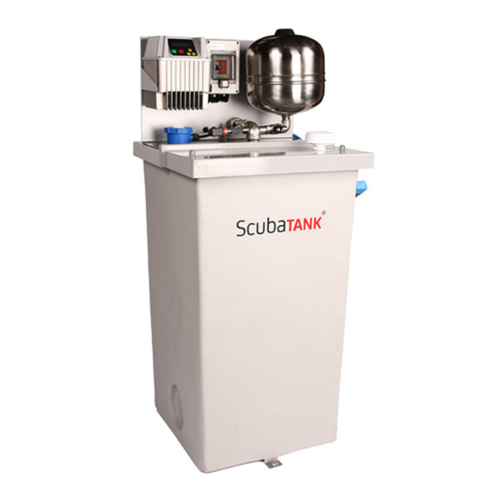
- Page 1 ScubaTANK WX Operation and Maintenance Manual Document Reference: DOC-WX1702...
-
Page 2: Table Of Contents
7. User Maintenance ..............................20 8. XPW Pump Maintenance............................21 9. Pressure Set Point Adjustment..........................23 10. Troubleshooting ..............................24 11. VASCO Inverter O&M Manual ..........................29 12. EC Declaration of Conformity..........................67 Dutypoint Limited Shepherd Road Gloucester GL2 5EL United Kingdom... -
Page 3: Important Safety Information
– Normal safety precautions must be taken and appropriate procedures observed to avoid accidents. Refer to Dutypoint for any technical advice or product information. It is the responsibility of the customer and/or the contractor: – To ensure that anyone working on the equipment is wearing all necessary protective gear/clothing;... - Page 4 Important Safety Information THE SYSTEM MUST ONLY BE OPERATED WHEN IT HAS BEEN CORRECTLY EARTHED AND PIPES BONDED TO EARTH IN ACCORDANCE WITH IEE REGULATIONS — When connecting external control wires care must be taken not to short circuit adjacent components. Bare cable ends which are not in use must be insulated.
-
Page 5: Specifications
Specifications Specifications Table 1: ScubaTANK WX Range Specifications Applications Water with no gas or aggressive substances Flow Range 0.8 - 3.1 litres/sec Pressure Range 2.0 - 7.0 bar Liquid Temperature 1°C - 23°C Ambient Temperature +5°C - +40°C for indoor installations... - Page 6 Specifications Table 2: Pump Ratings Power Supply to Control Power Output from Inverter to Pump Model Motor kW Rating Panel (V/Ph/Hz) Pump (V/Ph/Hz) Full Load Current (A) 3040-T230 0.55 3040-T230 0.75 3080-T230 3100-T230 5040-T230 0.75 230/1/50 230/3/50 5060-T230 5080-T230 10.5 5100-T230 9040-T230 10.5...
-
Page 7: Installation Sequence
Installation Sequence Installation Sequence 3.1 Position and Secure the Tank Connect the inlet water supply via an isolation valve; Connect the overflow system to a suitable drain; Connect the warning pipe (where fitted) and pipe to a suitable location; Connect the outlet pipe; Connect the electrical supply cable from a fused supply with correct rating - see ScubaTANK Breaker Ratings;... - Page 8 Installation Sequence Figure 3: Filter Cleaning Process 1. Turn isolator level to OFF position perpendicular to pipework 3. Remove filter and rise under water to remove build up 4. Replace all parts and turn isolator lever to ON position parallel to pipework 2.
- Page 9 CONNECTION 3.5 How to Seal a Horizontal Split Tank (Where Applicable) This section applies only to ScubaTANK WX models with horizontal split tanks. These have the -HS designation. WARNING: THE FLANGE SEALANT IS VERY ADHESIVE — Ensure it is aligned correctly before applying it to the flange.
- Page 10 Installation Sequence Figure 5: Applying split tank sealant Nut and bolt arrangement. Ensure flanges are clean Apply flange sealant and free from grease, grit ensuring the black strip is etc. water side. ✓ × When applying sealant to Flange sealant overlaps like DO NOT LEAVE A GAP the next flange, ensure a this.
- Page 11 Installation Sequence Table 5: ScubaTANK Level Probe Holder Details Solenoid Cut-Off Probe Shortest probe (300mm) Solenoid Cut-In Probe 100mm longer than the cut out probe Low Level Probe 50mm shorter than the common probe Common Probe Longest probe Note used in standard ScubaTANK models Figure 6: ScubaTANK Probes Table 6: ScubaTANK Level Probe Lengths...
-
Page 12: Commissioning
In practice, a system can almost invariably be made to perform more efficiently if further re-commissioning is carried out on site. Please note that engineer visits by Dutypoint are priced at one visit to commission one pump set. If there are multiple units on a site, special terms can be negotiated. - Page 13 Commissioning Figure 7: Terminal Wiring If installing a Dutypoint FS-series float switch, the following terminals should be used: LEVEL BROWN: Terminal 1 FLOAT BLACK: Terminal 2 FAILED SIGNAL BLUE: Not used - terminate safely FROM INVERTERS 4.5 Final Checks Before Commissioning Re-check all equipment for any accidental damage caused during installation.
- Page 14 The advised procedure should then be carried out individually for each pump in the pump set. 4.10 Programming the Controller Dutypoint Systems fit a design of Inverter/Controller that is most suitable for the design duty of the pump set. Manufacturer’s information for them is detailed in the Appendices to this manual.
- Page 15 Commissioning 4.13 Duty/Assist Twin Pump Sets For ‘Duty/Assist’ applications, run the system up to pressure using the ‘Duty’ Pump only, then deliberately create the condition(s) which will require the ‘Assist’ Pump to operate as well. (e.g: open taps to reduce the pressure in the system to a point where one pump only cannot maintain the required output.
-
Page 16: Operating The Pump Set
Operating the Pump Set Operating the Pump Set 5.1 VASCO Display The display screen on the VASCO is a back-lit LCD displaying 2 rows of 16 digits each. Alarms are indicated by an audible signal. Figure 9: VASCO Control Panel STOP Motor Enter Scroll Up/Down... - Page 17 — All full description of the advanced parameters is available in the appendix of this manual — For further assistance, call the Dutypoint Technical Service line of 01452 300590. Pressing ENTER when you are in the initial display will show the following menus:...
-
Page 18: Pressure Vessel
Pressure Vessel Pressure Vessel The pressure vessel supplied as part of your Dutypoint product is used to absorb and conserve the potential energy of pressurised liquid. Stored energy from liquid under pressure is transferred to the water system when required. - Page 19 Pressure Vessel Figure 11: Pre-Charging a Pressure Vessel 6.5 Diaphragm Replacement To replace a diaphragm: Empty the expansion tank Remove the pre-charging by releasing the air vent. Loosen the M8 screws fastening the flange Remove the flange Extract the diaphragm and replace it 6.6 Installing a Replacement Vessel Read these instructions carefully before installing the product: Make sure the product is in good condition.
-
Page 20: User Maintenance
Routine user maintenance for Dutypoint pump sets. Dutypoint pump sets have been designed to keep major maintenance requirements to a minimum. Planned maintenance of the pumps and other principal components should therefore be undertaken at the intervals recommended in the manuals referenced below. -
Page 21: Xpw Pump Maintenance
XPW Pump Maintenance XPW Pump Maintenance The following information is an extract from the pump manufacturer’s documentation. 8.1 Routine Maintenance The pump requires no detailed maintenance except to: – Periodically verify that the suction grate is clear; – Periodically with the power off, check the condition of the cables and electrical power and earth connections. 8.2 Pump Replacement WARNING: ELECTRICAL PUMPS SHOULD NEVER BE USED OUTSIDE THE LIMITATIONS DESCRIBED IN THE TECHNICAL SPECIFICATIONS... - Page 22 XPW Pump Maintenance If the direction of rotation is reversed due to incorrect connection or controller programming, the pump performance will be significantly lower than the nominal values. To verify a correct connection, proceed as follows: Start the electrical pump before it is submerged. Correct rotation is in a counter- clockwise direction as viewed from above. With the pump operating, installed and submerged, use a clamp meter to measure the current.
-
Page 23: Pressure Set Point Adjustment
Pressure Set Point Adjustment Pressure Set Point Adjustment Note: This procedure should only be undertaken by an experienced and qualified installer or engineer. Failure to follow the procedure correctly may cause damage to the product and invalidate any product warranty. The installer is responsible for ensuring that the required value is suitable for the product. -
Page 24: Troubleshooting
Troubleshooting 10 Troubleshooting Troubleshooting VASCO-equipped booster sets. The information in this section is common to all VASCO-equipped Dutypoint booster sets. For more detailed troubleshooting information that is specific to the type and model of pump controller used, please refer to the manufacturer’s literature in the Appendix. - Page 25 Check for the two green lights marked ‘Un’. If either are not illuminated there is a problem with the power supply to the Loss of power to probe relays probe relays. Contact Dutypoint Technical Service on 01452 300590 for assistance.
- Page 26 — You should only access the Installer and Advanced menus if you are trained to do so; — A full description of these is available in the Appendix to this manual; — For further assistance, call the Dutypoint Technical Service line on 01452 300590.
- Page 27 Troubleshooting Table 12: VASCO Controller Alarm Messages Message Alarm Description Possible Solutions Motor overload: input current of the motor is – Make sure that the motor current setting parameter is higher than the rated motor current setting higher than rated. parameter.
- Page 28 Make sure buttons are not depressed. A button on the keyboard has been pressed for KEYBOARD FAULT – If problem persists, call Dutypoint Technical Service more than 150 seconds. on 01452 300590. Check the input digital configuration (IN/OUT parameters ACTIVE DIG.IN.X...
-
Page 29: Vasco Inverter O&M Manual
VASCO Inverter O&M Manual 11 VASCO Inverter O&M Manual... - Page 30 VASCO Inverter O&M Manual 3. Technical Characteristics Power frequency: 50 - 60 Hz (+/- 2%) Max. ambient temperature at nominal current: 40°C (104 °F) Max. altitude at nominal current: 1000 m Grade of protection: IP55 (SIZE 1,2) , IP54 (SIZE 3) * RS485 serial communication * auxiliary cooling fan of the VASCO, used in wall mounted applications, has a protection rating of IP54.
- Page 31 VASCO Inverter O&M Manual 3.1 Weight and dimensions Weight * Size SIZE 2 SIZE 1 Model [Kg] VASCO 209 VASCO 214 VASCO 218 VASCO 225 VASCO 306 VASCO 309 VASCO 314 VASCO 318 VASCO 325 VASCO 330 SIZE 3 VASCO 338 VASCO 348 VASCO 465 VASCO 375...
- Page 32 VASCO Inverter O&M Manual 4. Electric wiring Power board VASCO 209,214 Power supply: Output: 230 V AC auxiliary fans LINE: L1, L2,GND 3 ph motor: (wall mounting kit) It is recommended to use GND,U,V,W, FAN: F1, F2 cable lugs 1 ph motor: earth, U (running), V (common) It is recommended to use cable lugs.
- Page 33 VASCO Inverter O&M Manual Power board VASCO 218, 225 Power supply: Motor output: 12 V dc auxiliary fans (wall mounting kit) LINE: L1, L2, GND MOTOR: U, V, W, GND VENT: +, - It is recommended to use cable It is recommended to use cable WARNING: respect the polarity.
- Page 34 VASCO Inverter O&M Manual Power board VASCO 306,309,406,409 Power supply: Motor output: 12 V dc auxiliary fan (wall mounting kit) : LINE: GND , L1, L2, L3, MOTOR: U, V, W, GND 0VE, + VE It is recommended to use cable It is recommended to use cable WARNING: respect the polarity.
- Page 35 VASCO Inverter O&M Manual Power board VASCO 314,318,325,330,414,418,425,430 Power supply: Motor output: 12 V dc auxiliary fans (wall mounting kit) LINE: L1, L2, L3, GND MOTOR: U, V, W, GND VENT: +, - It is recommended to use cable It is recommended to use cable WARNING: respect the polarity.
- Page 36 VASCO Inverter O&M Manual Power board VASCO 338,348,365,375,385,438,448,465,475,485 P.E. MOTOR LINE Power supply: Motor output: LINE: L1, L2, L3, P.E. MOTOR: U, V, W, P.E. It is recommended to use It is recommended to use cable lugs. cable lugs. Cable stripping recommended for line input and output to the motor.
- Page 37 VASCO Inverter O&M Manual Control board Analog inputs (10 or 15 Vdc): Digital outputs: RS485 for COMBO: AN1: 4-20 mA: sensor 1 motor run signal: AN2: 4-20 mA: sensor 2 NO1, COM1: closed contact with motor running. AN3: 4-20 mA / 0 - 10 Vdc (settable NC1,COM1: closed contact with motor stopped.
- Page 38 VASCO Inverter O&M Manual 4.1 Protections The protections required upstream each VASCOs depends on the type of installation, and local regulations. We recommend to use overload protection with the characteristic curve of type C and type B circuit breaker, sensitive to both AC and DC current.
- Page 39 VASCO Inverter O&M Manual 5. VASCO installation VASCO can be installed directly on the fan cover of the motor or mounted on the wall. Motor mounting kit In this application VASCO is cooled by the motor fan. Motor kit (available upon request) allows a solid coupling of the two units and it is composed of: VASCO SIZE 1 VASCO SIZE 2...
- Page 40 VASCO Inverter O&M Manual VASCO SIZE 3 n.° 1 motor feet adaptor for MEC160,180,200,225 n.° 4 M8 bolts, n.° 4 M10 bolts, nuts and washer...
- Page 41 VASCO Inverter O&M Manual Wall mounting kit In this application VASCO is cooled independently by its auxiliary cooling fan integrated in the radiator. Wall-mounted kit is composed of: VASCO SIZE 1 VASCO SIZE 2 n.° 1 auxiliary fan 230V AC (VASCO 209,214) n.°...
- Page 42 VASCO Inverter O&M Manual 5.1 VASCO Installation for constant pressure control VASCO controls the pump speed to maintain constant pressure at a set point independent of the water demand in the system. A basic schematic is shown below: 1: pump 2: check valve 3: pressure tank 4: valve...
- Page 43 VASCO Inverter O&M Manual 5.2 VASCO installation for differential constant pressure applications VASCO can manage the pump speed in order to keep constant the pressure difference between the dischage and suction side of the pump in circulation systems. To do this, it is usually installed a differential pressure sensor. Alternatively, it is possible to use two identical pressure sensors: one in suction side and one in discharge side of the pump.
- Page 44 VASCO Inverter O&M Manual 6. VASCO Use and Programming VASCO software is extremely simple to use, but allows a wide variety of parameters to be set for ideal system calibration. Setting Parameters are organized in 2 levels: 1: Installer level (MENU’ CONTROL PARAMETERS, MENU’ IN/OUT PARAMETERS, MENU’ CONNECTIVITY PARAM.) A password is required for this level;...
- Page 45 VASCO Inverter O&M Manual Parameter Default Description End user communication language Language XXXX XXXXXX Unit Unit XXXXX threephase Type of motor connected (VASCO 209,214) Motor type singlephase/threephase Rated current of the motor per it’s nameplate indication increased Rated motor Amp. by 10%.
- Page 46 VASCO Inverter O&M Manual 6.3 Initial view When first powering the VASCO, the display shows : release of display software (LCD = X.XX) and the release of inverter software (INV = X.XX) as shown below: LCD = X.XX INV = X.XX The following End User messages are displayed by pushing the scroll buttons: p is the pressure value read by the pressure transducer.
- Page 47 VASCO Inverter O&M Manual First row gives the VASCO status: Inv: ON XXX.X Hz VASCO is powered and is powering the motor showing its frequency. Inv: ON Mot: OFF VASCO is powered but motor is not running (i.e. motor/pump was stopped due to minimum frequency being reached) Inv: OFF Mot: OFF VASCO is not powered If COMBO function is activated, the VASCO address is placed close to indication “Inv”.
- Page 48 VASCO Inverter O&M Manual Parameter Default Description Maximum value allowed in the system. If the readen value goes over this value, an Max alarm value alarm occurs and the pump is stopped. Pump is automatically restarted if the XXX.X [bar] readen value goes below the maximum value for a period of at least 5 seconds.
- Page 49 VASCO Inverter O&M Manual Parameter Default Description To ensure proper operation of pressure control is recommended to place the sensor near the pump. To compensate the pressure loss in the pipes (proportional to flow) it is possible to vary the pressure set in a linear relation with respect to frequency.
- Page 50 VASCO Inverter O&M Manual Parameter Default Description again; otherwise, VASCO will stop the pump. Delta control Value drop below the set value required to restart the pump during control ramp. XXX.X [bar] press. Set value Delta control Control ramp Stop delay Freq.min.control Min mot.
- Page 51 VASCO Inverter O&M Manual Parameter Default Description Address VASCO address: 00 master 01 to 07 slaves Function to allow alternating between the VASCOs connected in COMBO (or pumps connected in DOL) in order to Alternance allow equal use of each pump in the group;...
- Page 52 VASCO Inverter O&M Manual Voltage boost Voltage increase during the motor start up. Warning: An excessive value can seriously damage the motor. Contact the XX.X [%] motor manufacturer for further information. Rated motor Amp. Rated motor current as per its nameplate indication increased by 5%. XX.X [A] Rated motor freq Rated motor frequency as per its nameplate.
- Page 53 VASCO Inverter O&M Manual V / f characteristic with which VASCO feeds the engine. The linear characteristic corresponds to constant torque with variable speed. The V/f lin. --> quad. quadratic characteristic is normally used with centrifugal pumps. The 85 % selection of torque characteristic should be done ensuring a smooth XXX [%] operation, a reduction of energy consumption and a lower level of heat...
- Page 54 VASCO Inverter O&M Manual Parameter Default Description Zero correction for analog input 2 (4-20 mA) Offset input 2 (20 mA x 20% = 4 mA). Zero correction for analog input 3 (0-10V) Offset input 3 (10V x 00% = 0 V). Zero correction for analog input 4 (0-10V) Offset input 4 (10V x 00% = 0 V).
- Page 55 VASCO Inverter O&M Manual 7. Protections and alarms Anytime a protection occurs a blinking message is displayed together with an audible alarm; on STATUS in the initial view, the protection is displayed; by pressing the STOP button. Only from this position (STATUS) in the initial view is it possible to try to reset the alarm;...
- Page 56 VASCO Inverter O&M Manual Check possible causes reaching min value Measured value has reached the lowest (i.e. broken pipe, open pressure relief valve, MIN. VALUE ALARM value accepted by the system. etc.) Check the min alarm value setting. The current drawn by the load exceeds the Increase the ramp-up time capacity of VASCO.
- Page 57 VASCO Inverter O&M Manual 8. Auxiliary pumps during constant pressure control When the water needs vary considerably, it is advisable to share the water request between several pumps ensuring better efficiency and reliability. A first method consists of a single pump driven directly by VASCO and another 1 or 2 pumps directly connected to the mains DOL (Direct On Line);...
- Page 58 VASCO Inverter O&M Manual 8.1 DOL pumps Each DOL pump is switched on by a contactor controlled by the digital output DOL1 and DOL2 present in the VASCO. VASCO relays driving the DOL pumps are relays with no voltage contacts. Max voltage to the contacts is 250 V, max current 5 A.
- Page 59 VASCO Inverter O&M Manual External switch Max 240 VAC, 5 A MANUAL Max 30 VDC, 5A Contactor AUTO Motor digital output 8.2 COMBO function In the “Control parameters” menu it is possible to enable the COMBO function that allows serial communication between up to 8 VASCOs, each one connected to a pump.
- Page 60 VASCO Inverter O&M Manual Inv: ON/OFF Mot: ON/OFF p_mis=XX.X [bar] 4. Scroll until: Menù ENT to access 5. Press ENT MENU’ Control. param. 6. Press ENT 7. Insert password (default 001). 8. Scroll until: Combo ON/OFF 9. Set ON 10. Set: VASCO’s address in parallel operation.
- Page 61 VASCO Inverter O&M Manual VASCO’s address in parallel operation. Address 01 --> 07: VASCO slaves 2. Press STOP (red button). 3. In the Motor parameters verify that Autorestart is set ON. 4. Press STOP (red button). 5. Press STOP again. Whenever the user accesses the Menu screen of the VASCO master, the communication between VASCOs is automatically interrupted.
- Page 62 VASCO Inverter O&M Manual 9. Trouble-shooting chart LCD does not switch on after powering Check the connecting flat cable between the LCD board (attached to the VASCO the cover) and the control board Check the fuses Check that the power cables are properly connected. Power line of VASCO is interrupted by Check the leakage current to ground of EMC filter the differential protection contactor...
- Page 63 VASCO Inverter O&M Manual 10. Technical Assistance For more technical information contact the authorized reseller providing the following information. The solution to the problem will be found faster and easier if full information is provided. Model/Serial Code LCD version (shown when VASCO is power INV version (shown when VASCO is power supplied) supplied)
-
Page 64: Declaration Of Conformity
VASCO Inverter O&M Manual DECLARATION OF CONFORMITY In according with: Machine Directive 2006/42/EC EMC Directive 2004/108/CE Low Voltage Directive 2006/95/CE R&TTE Directive 1999/05/EU VASCO is an electronic device to be connected to other electrical equipment with which it is to form individual units. It must, therefore, that the putting into service of this unit (with all its subsidiary equipments) to be performed by qualified personnel. - Page 65 VASCO Inverter O&M Manual NOTE Copyright NASTEC srl Nastec reserves the right to modify informations in this manual without any notice. Nastec srl, Via della Tecnica, 8, 36024, Mossano, Vicenza, Italy, Tel. +39 0444 886289, Fax +39 0444 776099, www.nastec.eu, info@nastec.eu...
- Page 66 VASCO Inverter O&M Manual NOTE Copyright NASTEC srl Nastec reserves the right to modify informations in this manual without any notice. Nastec srl, Via della Tecnica, 8, 36024, Mossano, Vicenza, Italy, Tel. +39 0444 886289, Fax +39 0444 776099, www.nastec.eu, info@nastec.eu...
-
Page 67: Ec Declaration Of Conformity
4104/30/EU: The Electromagnetic Compatibility Directive – 2006/95/EU: The Machinery Directive Hereby declare that the equipment: Description Dutypoint ScubaTANK WX Cold Water Booster Set Model Code WXx-xxxx-xxxx(-AB/-HS/-RM/2) Is in conformity with the applicable requirements of the following documents: – EN 809:1998+A1:2009: Pumps and pump units for liquids - Common safety requirements –... - Page 68 Dutypoint Limited Shepherd Road Gloucester GL2 5EL United Kingdom T: +44(0)1452 300592 W: www.dutypoint.com...
Need help?
Do you have a question about the ScubaTANK WX and is the answer not in the manual?
Questions and answers