
Subscribe to Our Youtube Channel
Related Manuals for COP-USA ash56nvir


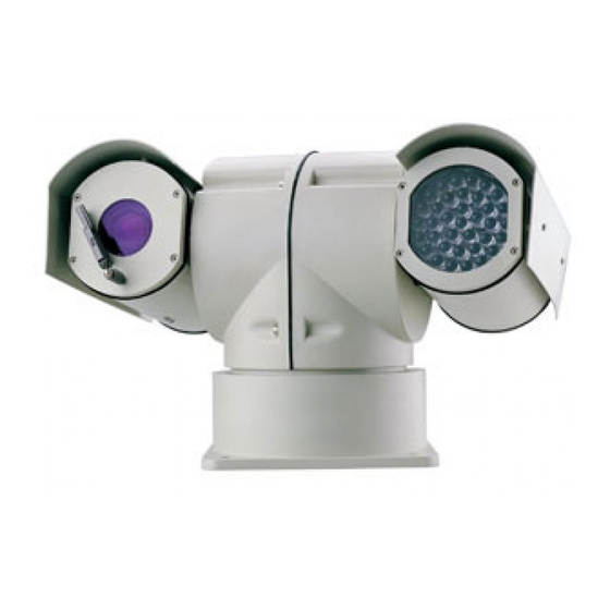
Summary of Contents for COP-USA ash56nvir
- Page 1 Operation Manual of Outdoor High-Speed Pan/Tilt with Infrared Lighting VER: 2.0 Please read the manual carefully before using the product. Safe Note:...
- Page 2 Note: To avoid electric shock danger, please don’t open. Note: To avoid electric shock, please don’t dismantle by yourself. There is not parts can be dismantled by user himself, should be maintained by qualified. The arrowhead sigh shined in triangle to remind user the non-insulated dangerous voltage appearing near the product is dangerous to human beings.
-
Page 3: Table Of Contents
Note………………………………………………………………………………5 The first chapter Function………………………………………7 1.1 P/T/Z spec……………………………………………………………………7 1.2 P/T/Z basic parameter………………………………………………………7 1.3 Infrared parameter……………………………………………………………7 1.4 P/T/Z alarm……………………………………………………………………7 1.5 Camera parameter………………………………………………………………8 1.6 P/T/Z function………………………………………………………………9 The second chapter menu setup……………………………………………………12 System connect pic………………………………………………………………12 2.1 Menu basic operation………………………………………………………13 2.2 Menu setup………………………………………………………………………13 2.2.1 MAIN MENU ……………………………………………………… 13 2.2.2 DISPLAY SETUP ………………………………………………13 2.2.3 CAMERA SETUP………………………………………………14 2.2.4 CONTROL SETUP……………………………………………14... - Page 4 4.2 Notice……………………………………………………………………22 4.3 Environment request…………………………………………………………22 4.4 Route safe………………………………………………………………22 4.5 Installation prepare……………………………………………………23 4.6 Installation way introduction………………………………………… 24 4.7 Installation spec……………………………………………………………25 4.7.1 Sun Shield installation………………………………………25 4.7.2 On Vehicle installation…………………………………………………25 4.7.3 Wall installation……………………………………………………26 4.8 P/T/Z line out way ……………………………………………………………… 27 Appendix:Usual trouble analysis…………………………………………29 Appendix:24VAC distance relation between route and transmission distance…30 Appendix:lightning strike proof, surge……………………………………31 Appendix:Maintenance service terms………………………………32...
-
Page 5: Note
Notes for Attention: Read the manual carefully before installing the product. Electric safe Observe all national and area electric safety standards in application. Adopt special power supply attached the product. There are two input ways of power supply: DC12V (vehicle) and AC24V (normal pan/tilt). Observe all electric safety standards in application and adopt special power supply attached the product. - Page 6 Don’t storage, install and use the product in inflammable, explosive dangerous eare. Do not apply the product under the state exceeding limited temperature, humidity or specifications of power supply. Please don’t dismantle parts inside device to effect using, there is no parts inside can be maintained by user himself.
- Page 7 The first chapter Description of Functions This product is a high-tech monitor and controller which incorporates high definition color camera, universal variable pan/tilt, infrared lighting, multi-functional decoder, character superimposing, alarm input/output into a whole, reduces interconnections to a great extent among parts in the system and rises up the reliability of the system.
- Page 8 1.4 Alarm Four Channel Inputs Normal Open, closing for alarm One Channel Output Normal Open, Normal Close Output 1.5 Camera Functions 18× 22× 23× 27× Model Color Synchronization Inside/Outside System Image Sensor 1/4″Exview HAD CCD Scan System 2:1 scan separate line Horizontal ≥480TVL Resolution...
- Page 9 Magnification Automatic/Manual Signal/Noise Ratio ≥50dB Signal/Noise Ratio Compound Signal 1.0Vp-p/75Ω 1.6 Pan/Tilt Functions This product is a high-tech monitor and controller which incorporates high definition color camera, universal variable pan/tilt, infrared lighting, multi-functional decoder, character superimposing, alarm input/output into a whole, reduces interconnections to a great extent among parts in the system and rises up the reliability of the system.
- Page 10 with selectable baud rates from 2400 bps to 19200 bps. 1.6.4 Camera Function: Refer to Camera Control Mode of Focal Length: the user can manually adjust the focal length of the camera. Control of Magnification:the user can “pull up” or “push away” the lens Backlight Compensation:...
- Page 11 Picture one The alarm input should be the input signal with the switch type. Any other types of the input signal (such as voltage signal) could damage the dome camera. In case multiple channels have alarm signals, the pan/tilt shall response upon them on by one with the interval of 2 seconds.
- Page 12 The second chapter Setup of the Menu of the Pan/Tilt Schematic Drawing of Pan/tilt: 1)Schematic Drawing of the Vehicle-Carried Pan/Tilt (the shock absorber is added), see picture 2: Monitor Video input SELECTED ON-LINE Keyboard R S485 BU S Al ar m Alarm Box Picture 2 2)Schematic Drawing of Common Pan/tilt, see picture 3:...
-
Page 13: Main Menu
2.1 Basic Operation of the Menu Open the main menu by the control keyboard or the matrix through the order “calling the 64th preset position” or the order in 4 seconds “calling the 1st preset position” in two fast and consecutive times. (There is no other control orders during the two calling times) When the menu is displayed on the screen, operate “TILT UP”, “TILT DOWN”... -
Page 14: Camera Setup
ID POS: to set the display position of the pan/tilt, which can be at four corners of the screen such as TOP-L (upper left), TOP-R (upper right), BOTT-R (bottom right) and BOTT-L (bottom left). TITLE DIS:when it is set at ON, the title of the preset position can be displayed on the left side of the screen when calling the preset position, such as “NO.001 ABCDEFGH”. -
Page 15: Control Setup
2.2.4 CONTROL SETUP ALARM:ON/OFF Turn on or Turn off the alarm input function. CO N TR O L SETU P 1. ALARM HOME OPTION:To enter into the sub-menu of automatic home 2. HO M E O PTI O N 3. I R- LED O FF function. -
Page 16: Camera Mask Set
return home. The time can be from 1 to 99 minutes. RETURN:To return the menu one level upward. 2.2.6 CAMERA MASK SET CA M ER A M A SK SET MASK PRIVACY:ON-open/OFF-close. 1. M ASK PRI UACY O N 2. M ASK SHAD E BLACK MASK SHADE:... - Page 17 speed by PAN LEFT/PAN RIGHT and press OPEN button to exit the menu. The start position and the end position of the pan can be set up by options 1 and 2 of the menu. SET PATROL:To run patrol of multiple positions. Select the number of the pattern by PAN LEFT/PAN RIGHT and press OPEN button to exit the menu.
- Page 18 POS is from 1 to 63 and 65 to 128. When POS is “---“, it means the range of the patrol is finished. The settable range of SP is from 0 to 8 (0 is the same with 1 and has the fastest speed while 8 has the lowest speed).
- Page 19 The third chapter Setup of the Intelligence Full-Dome Pan/Tilt Before installing the product, first of all confirm the communication protocol and the baud rate of the main machine in the system, then set the dip-switch SW2 of the pan/tilt to be identical with that of the system, set the address of the pan/tilt on SW1 and the type of the communication protocol and the baud rate on SW2.
- Page 20 States of Dip-Switch Dome Address DIP-1 DIP-2 DIP-3 DIP-4 DIP-5 DIP-6 DIP-7 DIP-8 DIP-9 DIP-10 … … 1023 For example:...
- Page 21 3.3 protocol and default baud rate setup SW2 is used to set the communication protocol and the baud rate used by the pan/tilt. Bits from DIP-4 to DIP-1 of the SW2 are used to select the protocol and 16 different protocols can be selected in maximum. The encoded table of the protocol selected by the pan/tilt is as follows: Selection of Communication Protocol Normal Baud Rate Type or Protocol...
- Page 22 9600bps 19200bps Schematic Drawing of Dip-Switch for Reference: B01/ 9600Bps PAN ASO N I C / 9600Bps KALATEL/ 4800Bps PELC O - P/ D / 2400Bps ALEC / 9600Bps PELC O - P/ D / 4800Bps PELC O - M K/ 4800Bps U l t r ak/ 9600Bps...
-
Page 23: Safe Measure
The fourth chapter Installation of the Product 4.1 safe measure 4.1.1 Competency requirement to install or maintain Take on the qualification on CCTV installation or maintain, and qualification of relative work(such as high air work and so on),must have the rudimentary know ledge and operation skill as follows; Have rudimentary knowledge and operations skill on CCTV systems and makeup parts;... -
Page 24: Installation Prepare
Temperature : -35 ~55 ,Humidity:90% Power supply:DC12V/5A(Vehicle), AC24V/2.5A(Normal) 4.4Routing safe There must be more than 50meters between signal transmission line and high voltage cable routing inside should the best long eave, in hollow place must adopt sealed tube inter ground routing,and adopt one point to the ground to the tube,do not adopt routing in air in strong thunderstorm or high inductive pressure area( such as high pressure transformer substation), must adopt extra high power defend lighting equipment and install lighting rod and so on measures. - Page 25 Remark: make sure wall of installation, bracket must can bear total weight of P/T/Z and installation structure; having 4 speed times safe coefficient is required! 4.5.4 Setup dial switch Setup dial switch according to control protocol and P/T/Z address ( refer to P/T/Z parameter setup). “...
-
Page 26: Installation Spec
A、Vehicle –Carried installation mode B、wall installation mode About the 2 kinds of installation mode, detailed spec is appeared on the subsequent part in the manual operation. 4.7 Installation spec Prepare: 1)Remove the bottom plate of the pan/tilt; 2)Set the corresponding information in accordance with the schematic drawing of the dip-switch of addresses, protocols and baud rates;... -
Page 27: On Vehicle Installation
under pan Picture 2 4.7.1 Cover installation: 1)Take out 4 M3×5 crossed stainless steel screws and 4 3.2×8×0.7 four fluorine washers and housing from accessories. 2)Fix the housings at the hoist pole in frame at two sides with 4 M3×5 crossed stainless steel screws and 4 3.2×8×0.7 four fluorine washers (... -
Page 28: Wall Installation
prepared by user himslef picture 4 picture5 3)Fix the absorber at the under pan of P/T/Z with 4 M8 x 30 stainless steel bolts and one flip pillow , one flat pillow, see picture 6 M8 bolt Flip pillow Flat pillow Picture 6 4.7.3 Wall installation 51)Take the wall bracket out of packing, use the under pan as templet, drill 4 M8 metal bulgy bolt holes on the surface with strike electric drill, fit on bulgy tube separately ( see picture 7);... -
Page 29: P/T/Z Line Out Way
hole bulgy tube, installation hole picture 7 2)take P/T/Z out of packing, thrill through bracket with control line, video line, power line, and fix the bracket on the wall with 4 M8 bolts and oneφ8 flip pillow, 2 φ8×φ18 stainless steel flat pillows ( see picture 3)Then fix P/T/Z on the wall bracket with 4 M8 x 30 stainless steel bolts and flat pillow, flip pillow, nuts ( see picture 9). - Page 30 Description of 7-Core Terminal picture 10 Description: S.N. MEAN 1. DC12V(AC24V): RED 2. GND(AC24V): BLACK 3. R- (communication-): YELLOW 4. Null 5. R+ (communication+): ORANGE 6. V+: (VF+) V-: (VF-) 7. Description of 7-Core Terminal line out 4.8.2 Description of 10-Core Terminal see picture 11:...
- Page 31 Description of 10-Core Terminal picture 11 decription: S.N. MEAN Alarm-1 in: RED 1. 2. Alarm-2 in: ORANGE Alarm-3 In: YELLOW 3. Alarm-4 In: GREEN 4. 5. Alarm In COM: BLACK 6. Alarm Out COM: WHITE 7. 8. Alarm NO out: BLUE 9....
- Page 32 Appendix Normal Troubles and Remedies Troubles Possible Causes Remedies Power supply damaged of Replace insufficient electric power Wrong connection of power supply No action and images after Make correction switching on wires Engineering circuits failed Repaire Mechanic trouble Repair Abnormal self-inspection, images with humming of Pan/tilt may be inclining Re-fix...
- Page 33 you meet other special problem, you can contact with the dealer directly for technical support. :Relation form between 24VAC routing and communication distance Appendix When routing is confirmed, 24VAC pressure is lower than 1 0 %,the largest communication distance recommended. ( for equipments supply AC, the biggest pressure waste rate allowed is 1 0 %)。For example: the rated power of one equipment is 80VA,the needed smallest routing is 0.8000mm when be installed 35inch form transformer .
- Page 34 14(4) 22(6) 35(10) 90(27) Appendix :Prevent lightning strike, surge The product adopt TVS plate lightning strike technology, can prevent damage to instantaneous lightning strike, surge and so on kinds of pulse signal of lower than 1.5KW power efficiently. But, about install indoor, should to do necessary defense measures under the premise of assuring electric safe:...
-
Page 35: Appendix:maintenance Service Terms
图12 Video lightning arrester, communication lightning arrester, power lightning arrester, lightning rod, P/T/Z must be installed in the around of 45°under lightning rod, earth resistance line is on more than 4Ω, steel pipe sleeve Appendix : Maintenance service terms 1、Service range In one year the cargo sold, the problem is approved caused by product material or techniques defect, manufacturer will repair or replace for free;... - Page 36 Trouble products over warranty period, we do repay maintenance service lifetime. whole machine is repaired for free for 3 years( remark: camera module for 1 year) 2、Repair for free terms Cargoes need repair during repair for free period, buyer connect manufacturer to get RAN, and provide product information below along with cargoes;...
Need help?
Do you have a question about the ash56nvir and is the answer not in the manual?
Questions and answers