Table of Contents

Related Manuals for IAI SCON-CB-F


Summary of Contents for IAI SCON-CB-F
- Page 1 SCON-CB Series Controller Servo Press Function Instruction Manual Fifth Edition CB-F Standard Type LC-F PLC Feature Equipped Type CGB-F Safety Category Complied Type Safety Categories Complying LCG-F PLC Feature Equipped Type IAI Corporation...
- Page 3 This Instruction Manual is original. The product cannot be operated in any way unless expressly specified in this Instruction Manual. IAI shall assume no responsibility for the outcome of any operation not specified herein. Information contained in this Instruction Manual is subject to change without notice for the purpose of product improvement.
- Page 5 Construction of Instruction Manual for Each Controller Model and This Manual SCON-CB/CGB Servo Press Type Basic Function • Press Program Operation SCON-CB-F/CGB-F (This Manual) ME0345 • Serial Communication Serial Communication [Modbus] ME0162 ★ Types to Select From • PIO Control •...
- Page 6 Table of Overall Contents Name for Each Parts and Their Functions In this chapter, explains name for each parts and their functions. About SCON-LC Type In this chapter, explains the outline of LC (equipped with PLC feature) type. Chapter 1 Specifications Check In this chapter, explains about the specifications, current amperage, model codes and so on for the products.
-
Page 7: Table Of Contents
Table of Contents Safety Guide ···································································································· 1 Precautions in Operation ···················································································· 8 International Standards Compliances ··································································· 11 Name for Each Parts and Their Functions ·····························································12 About SCON-LC Type·······················································································18 Actuator Axes··································································································20 Chapter 1 Specifications Check ······································································· 21 1.1 Product Check································································································· 21 1.1.1 Parts ·······································································································... - Page 8 2.4 Controller for Motors of 3000W and above····························································· 88 2.4.1 Wiring for Power Supply Circuit ····································································· 88 2.4.2 Wiring of Emergency Stop Circuit (System I/O) ················································· 92 2.4.3 Connection of Actuator ················································································ 94 2.4.4 Connection of PIO ······················································································ 96 2.4.5 Multi-function Connector ··············································································...
- Page 9 Chapter 9 Appendix ·····················································································199 9.1 Way to Set Multiple Controllers with 1 Teaching Tool ·············································· 199 9.1.1 Connecting Example················································································· 199 9.1.2 Detailed Connection Diagram of Communication Lines····································· 200 9.1.3 Axis No. Setting ······················································································· 201 9.1.4 Handling of e-CON Connector (How to Connect) ············································ 202 9.1.5 SIO Converter ·························································································...
- Page 11 Field Network Setting File 6) Each Actuator Instruciton Manual (EDS File etc.) Download it in IAI homepage. (http://www.iai-robot.co.jp/) Step 2 Check How to Operate This product is a controller dedicated for servo press function. (It cannot conduct positioner operation or pulse train control.)
- Page 12 Check the operation modes and control methods available on the controller you have purchased. It can be defined on the controller model code shown on the label in the front face of the controller. Type Name 1) CB / CGB (Positioner) 2) LC / LCG (Ladder control) Encoder Option 1) F (dedicated for Servo Press Function)
- Page 13 • Heat Radiation and Installation Keep the ambient temperature of the controller at 40C or less. To fix the units in the control box, use the attachment holes on top and bottom of the unit for the screw-fixed type. Install in the orientation shown in the figure below for heat radiation. 10mm or more Air Flow 100mm...
- Page 14 Step 4 Wiring Refer to Chapter 2 “Wiring” Refer in Chapter 4 for Fieldbus Type. ●Example for Basic Connection 1 (~ 750W or less) Regenerative Resistor Unit (RESU-2 : option) Required depending on usage condition (Note1) Power Source for CB-SC-REU010 (Note1) I/O Control 24V DC...
- Page 15 Step 5 Operation How you should look in the instruction manuals will differ depending on the operation modes and control methods you choose. Establish the settings for your operation needs. ● For Operation with PIO Control Chapter 3. Operation Instruction Manual for Each Fieldbus ●...
-
Page 17: Safety Guide
Safety Guide “Safety Guide” has been written to use the machine safely and so prevent personal injury or property damage beforehand. Make sure to read it before the operation of this product. Safety Precautions for Our Products The common safety precautions for the use of any of our robots in each operation. Operation Description Description... - Page 18 Operation Description Description Transportation ● When carrying a heavy object, do the work with two or more persons or utilize equipment such as crane. ● When the work is carried out with 2 or more persons, make it clear who is to be the leader and who to be the follower(s) and communicate well with each other to ensure the safety of the workers.
- Page 19 Operation Description Description Installation (2) Cable Wiring and Start ● Use our company’s genuine cables for connecting between the actuator and controller, and for the teaching tool. ● Do not scratch on the cable. Do not bend it forcibly. Do not pull it. Do not coil it around.
- Page 20 Operation Description Description Installation (4) Safety Measures and Start ● When the work is carried out with 2 or more persons, make it clear who is to be the leader and who to be the follower(s) and communicate well with each other to ensure the safety of the workers. ●...
- Page 21 Operation Description Description Trial ● When the work is carried out with 2 or more persons, make it clear who Operation is to be the leader and who to be the follower(s) and communicate well with each other to ensure the safety of the workers. ●...
- Page 22 Operation Description Description Maintenance ● When the work is carried out with 2 or more persons, make it clear who is to be the leader and who to be the follower(s) and communicate well Inspection with each other to ensure the safety of the workers. ●...
- Page 23 Alert Indication The safety precautions are divided into “Danger”, “Warning”, “Caution” and “Notice” according to the warning level, as follows, and described in the Instruction Manual for each model. Level Degree of Danger and Damage Symbol This indicates an imminently hazardous situation which, if the Danger Danger product is not handled correctly, will result in death or serious...
-
Page 24: Precautions In Operation
Precautions in Operation 1. Use the following teaching tools. In this controller servo press function for only use the PC sotware. [Refer to 1.1.2 Teaching Tool.] 2. Backup the data to secure for breakdown. A non-volatile memory is used as the backup memory for this controller. All the registered press program and parameters are written into this memory and backed-up at the same time. - Page 25 6. About the create a sequence program Please note the following when create a sewuence program. To certainly transfer the signal between controllers with different scan time, it is necessary to have longer scan time than the one longer than the other equipment. (To ensure to end the process safely, it is recommended to have the timer setting more than twice as long as the longer scan time at least) ●...
- Page 26 IAI products equip a built-in drive cutoff relay considering customer’s usage. However, as described above, whether it can be used or not relies on such facts as the safety demand level and frequency of drive cutoff.
-
Page 27: International Standards Compliances
This product comply with the following international standards: Refer to Overseas Standard Compliance Manual (ME0287) for more detailed information. Controller RoHS Directive CE Marking Please contact IAI (to 750W) SCON-(For Servo Press) (3000 to 3300W) 1. Use Environment • It can be used in pollution degree 2 environment. -
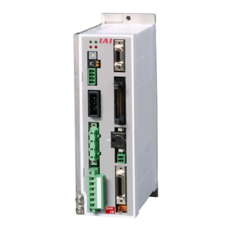
Page 28: Name For Each Parts And Their Functions
Name for Each Parts and Their Functions ● ~750W Type 9) Multi-Function 8) Status Indicator LED Connector 7) Axis No. Setting Switch 6) Piano Switch 10) PIO Connector (Not to use) 5) System I/O Connector 11) Operation Mode Setting Switch 4) Regenerative Unit Connector 12) SIO Connector... - Page 29 6) Piano Switch Not to use. 7) Axis No. Setting Switch (ADRS) This switch is used to set an axis number in multi-axis operation through serial communication. Using the SIO converter allows multiple axes to be controlled on a teaching tool such as a PC without connection/disconnection of the connection cable connector.
- Page 30 9) Multi-Function Connector (MF I/F) [Refer to 2.1.2 [7] Multi-Function Connector] It is a connector to use the feedback pulse output, analog output of loadcell load data and SIO communication function (SIO2). 10) PIO Connector (PIO) [Refer to 2.1.2 [5] PIO Circuit] The PIO connector is used for control I/O signals.
- Page 31 ● ~3000W Type 10) Status Indicator LED 9) Charge Status Display LED 8) Internal Regenerative Resistor Valid Connector 7) Regenerative Unit Connector 11) Multi-Function Connector 6) Motor Connector 12) PIO Connector 5) Piano Switch 13) Operation Mode (Not to use) Setting Switch 4) Axis No.
- Page 32 4) Axis No. Sttting Switch (ADRS) This switch is used to set an axis number in multi-axis operation through serial communication. Using the SIO converter allows multiple axes to be controlled on a teaching tool such as a PC without connection/disconnection of the connection cable connector. The SIO converter can specify up to 16 axes with hexadecimal numbers 0 to F.
- Page 33 11) Multi-Function Connector (MF I/F) [Refer to 2.3.2 [7] Multi-Function Connector] It is a connector to use the feedback pulse output, analog output of loadcell load data and SIO communication function (SIO2). 12) PIO Connector (PIO) [Refer to 2.3.2 [5] PIO Circuit] The PIO connector is used for control I/O signals.
-
Page 34: About Scon-Lc Type
■About SCON-LC Type■ LC Type is equipped with a built-in PLC feature, and is capable to control SCON with ladder programs instead of the host PLC if the programs are in small scale. CB Types are Control available with ladder programs equipped with PLC instead of host PLC feature... - Page 35 ●Operation Pattern (Assignment) 1) The operation pattern is to be set in Parameter No. 84 “Fieldbus Operation Mode”. Parameter No.84 Setting Operation Pattern Remote I/O mode Full Functional Mode The set operation patterns are assigned to the internal relay (input signals to M2048 to 2063, output signals to M2304 to M2319).
-
Page 36: Actuator Axes
Actuator Axes Refer to the pictures below for the actuator axes that can be controlled. 0 defines the home position. * The home position cannot be set at the end that the rod is extended (home reversed type). Rod Type... -
Page 37: Chapter 1 Specifications Check
Chapter 1 Specifications Check 1.1 Product Check 1.1.1 Parts This product is comprised of the following parts if it is of standard configuration. If you find any fault in the contained model or any missing parts, contact us or our distributor. Part Name Model Remarks... - Page 38 Part Name Model Remarks DP-5 Enclosed for Dummy Plug SCON-CGB/LCG Shown in the figure is an Safety Guide image. Shown in the figure is an First Step Guide image. Shown in the figure is an Instruction Manual (DVD) image.
-
Page 39: Teaching Tool
TB-03 1.1.3 Instruction Manuals Related to this Product, which are Contained in the Instruction Manual (DVD) Name Manual No. SCON-CB-F/CGB-F/LC-F/LCG-F Servo Press Function ME0345 Instruction Manual PC Software RCM-101-MW/ RCM-101-USB Instruction Manual ME0155 Touch Panel Teaching TB-02/02D Applicable for Position... -
Page 40: How To Read The Model
1.1.5 How to Read the Model S C O N – C B- 200 I F - N P - 3 - 1 - ** <Identification for IAI use only> <Series> * There is no identification in some cases <Type>... -
Page 41: List Of Basic Specifications
1.2 List of Basic Specifications 1.2.1 Specification List SCON-CB-F/CGB-F Item Less than 400W 400 to 750W 3000W or more Applicable Motor Capacity 30W to 399W 400W to 750W 3000W to 3300W Single-phase AC100 to 115V Single-phase AC200 to 230V Three Phase AC200 to 230V... - Page 42 SCON-CB-F/CGB-F Item Less than 400W 400 to 750W 3000W or more Surrounding Air Temperature 0 to 40°C Surrounding Humidity 85%RH or less (should be no condensation or freeze) Surrounding Environment [Refer to 1.6 Installation and Storage Environment] Surrounding Storage Temperature -20 to 70°C (should be no condensation or freeze)
-
Page 43: Item For The Power Capacity And Heating Value
1.2.2 Item for the Power Capacity and Heating Value Rated Power Capacity = Motor Power Capacity + Control Power Capacity Peek Max. Power Capacity = Peek Max. Motor Power Capacity + Control Power Capacity Wattage of Motor Power Peek Max. Motor Control Power Rated Power Peek Max. -
Page 44: External Dimensions
1.3 External Dimensions 1.3.1 SCON-CB/CGB/LC/LCG less than 400W min80 In Absolute Battery Attachment (Absolute Encoder Type) It is not necessary when using Pulse Train Control because it does not comply with it. 1.3.2 SCON-CB/CGB/LC/LCG 400W to 750W min80 In Absolute Battery Attachment (Absolute Encoder Type) It is not necessary when using Pulse Train Control because it does not comply with it. -
Page 45: Scon-Cb/Cgb/Lc/Lcg 3000W To 3300W
1.3.3 SCON-CB/CGB/LC/LCG 3000W to 3300W (15.7) 92.7... -
Page 46: External Interface Specifications
1.4 External Interface Specifications 1.4.1 Standard Input Output Interface Specification (Multi-Function Connector) There are 3 types in the external interface mounted in the standard. 1) Serial Communication Interface 2 (For display device etc.) 2) Analog Output (Load of loadcell) 3) Encoder Feedback Pulse Output 1) Serial Communication Interface 2 (SIO2) Type Serial communication interface 2 is to be assigned to the multi-function connector, it is to be used for connection to a touch panel or display. -
Page 47: Input Output Interface Specification Dedicated For Pio Type
1.4.2 Input Output Interface Specification dedicated for PIO Type [1] Signal I/O type dedicated for 24V (Note) The function of each signal is fixed and cannot be used for general purpose. Input Section Output Section Input Voltage 24V DC ±10% Load Voltage DC24V Peak Load... -
Page 48: Filedbus Type Specifications
1.4.3 Filedbus Type Specifications [1] DeviceNet Specifications Item Specification Communication Standard DeviceNet 2.0 Group 2 only Server Network-Powered Insulation Node Baud Rate Automatic Tracking to Master Communication System Master-Slave System (polling) Number of Occupied • 1CH (Remote I/O mode) Channels •... - Page 49 [3] PROFIBUS-DP Specifications Item Specification Baud Rate Automatic Tracking to Master Communication System Hybrid System (Master-Slave System or Token Passing System) Number of Occupied Bytes • 2byte (Remote I/O mode) • 32byte (Full function support mode) Communication Cable Max. Total Network Baud Rate Cable Type Length...
- Page 50 [6] EtherNet/IP Specifications Item Specification Baud Rate 10BASE-T/100BASE-T (It is recommended to Auto Negotiation setting) Depends on EtherNet/IP specification Communication Cable Length (Distance between hub and each nodes: 100m max.) Number of Connection Depends on master unit Applicable Node Address 0.0.0.0~255.255.255.255 Number of Occupied Bytes •...
-
Page 51: Options
1.5 Options 1.5.1 Regenerative Unit for Motors of up to 750W It is a unit to convert the regenerative current generated at motor deceleration into heat. Refer to 2.2.6 Connection of Regenerative Unit for the number of connectable units. [Model, Accessories] Item Accessories Screw affixed standard type... -
Page 52: Regenerative Unit For Motors Of 3000W And Above
1.5.2 Regenerative Unit for Motors of 3000W and above It is a unit to convert the regenerative current generated at motor deceleration into heat. Refer to 2.4.6 Connection of Regenerative Unit for the number of connectable units. [Model, Accessories] Accessories Model RESU-35T None... -
Page 53: Brake Box: Rcb-110-Ra13-0
1.5.3 Brake Box: RCB-110-RA13-0 Brakes for two axes can be controlled with one brake box. This is necessary when connecting an actuator with indication to connect a brake box. [Specifications] Item Specification Main Unit Dimension 162×94×65.5mm Power supply Voltage, Current DC24V±10% 1A Connection Cable Encoder Cable (Model CB-RCS2-PLA010) 1m... -
Page 54: Load Cell
1.5.4 Load Cell The pressing operation using force sensor. [Specifications] Item Specification Loadcell System Strain Gauge Rated Capacity [N] 2000 6000 20000 50000 (Note 1) Allowable Oberload [%R.C*] Lordcell Accuracy ±1.0 ±1.0 ±1.0 [%R.C*] Ambient temperature range [°C] 0 to 40 Dielectric strength voltage [V] DC50 * R.C: Rated Capacity... -
Page 55: Pulse Converter: Jm-08
1.5.5 Pulse Converter: JM-08 It converts the differential system feedback pulse into the open collector specification. Use this converter if the host controller sends pulses input in the open collector mode. [Specifications] Item Specification Input Power Supply DC24V±10% (MAX. 50mA) Input Pulse Differential output equivalent to 26C32 (MAX. -
Page 56: Installation And Storage Environment
1.6 Installation and Storage Environment This product is capable for use in the environment of pollution degree 2 or equivalent. *1 Pollution Degree 2 : Environment that may cause non-conductive pollution or transient conductive pollution by frost (IEC60664-1) [1] Installation Environment Do not use this product in the following environment. -
Page 57: Noise Elimination And Mounting Method
1.7 Noise Elimination and Mounting Method (1) Noise Elimination Grounding (Frame Ground) Other Controller equipment Connect the ground cable using the tapped hole for FG Controller connection (PE terminal for 3000W and higher) on the main unit. Other Other Controller equipment equipment Use a copper wire cable with its width... - Page 58 (4) Heat Radiation and Installation Design and Build the system considering the size of the controller box, location of the controller and cooling factors to keep the surrounding temperature around the controller below 40°C. Also, set up a fan to keep the ambient temperature even. ●For Controller for Motors of up to 750W 10mm or more Air Flow...
- Page 59 ●For Controller for Motors of 3000W and above 100mm or more 150mm or more 50mm or more 30mm or more 50mm or more 30mm or more Air Flow...
-
Page 61: Chapter 2 Wiring
Chapter 2 Wiring The servo press type SCON can select PIO or fieldbus* as the control method of the host controller. * Select when purchasing. Cannot be changed after purchased. Applicable fieldbus: CC-Link, DeviceNet, PROFIBUS-DP, CompoNet, MECHATROLINK-Ⅰ/Ⅱ, EtherCAT, EtherNet/IP, PROFINET-IO There is no actual difference in cable wiring between CB/CGB Types and LC/LCG Types. -
Page 62: Wiring
2.1.2 Wiring [1] Main Power Circuit L1 L2 Circuit Breaker SCON Power Supply Connector Earth Leakage Breaker Motor Power Supply Noise Filter Control Power Supply Surge Protector Grounding resistance at 100Ω or less (Grounding Class D) (Note) The power voltage of the controller (100V AC or 200V AC) cannot be changed. [2] Brake Power Supply Circuit 24V DC SCON... - Page 63 [3] Actuator Emergency Stop Circuit (System I/O connector) As an example of a circuit, cases of 3 conditions are shown. Select from 2) or 3) for CGB/LCG type. ★ Reference: Operate the actuator for try (Note: It is not emergency stop) 1) Operate actuator with the equipment and emergency stop of teaching tool input (EMG-) activated 2) Stop supplying external motor power at emergency stop input 3) Shut off the motor power externally by inputting the emergency stop with using two units of...
- Page 64 2) Stop supplying external motor power at emergency stop input Short-circuit in PC software cable Emergency Emergency EMG A EMG B stop switch stop reset switch System I/O connector SIO connector (Note 3) Emergency stop circuit exclusive use (Note 1) (Note 4) AC power supply Motor power...
- Page 65 3) Shut off the motor power externally by inputting the emergency stop with using two units of controllers or more. Short-circuit in PC software cable Emergency stop Emergency stop reset switch switch System I/O SIO connector connecter (Note 3) Emergency stop circuit exclusive use 24V EMG+ (Note 1)
- Page 66 [4] Motor • Encoder Circuit Use the dedicated connection cables for the connection between an actuator and controller. 1) Connecting the single axis robots (except for RCS2-RA13R) SCON (Note 1) Encoder Cable Encoder Connector Motor Connector (Note2) tor Cable Note 1 Applicable Connection Cable Model Codes □□□ : Cable Length Example) 030 = 3m Actuator Series Name Cable CB-RCS2-PLDA□□□...
- Page 67 3) Connecting the RCS2-RA13R with loadcell (with brake) Brake Box CB-RCS2 (RCB-110-RA13) -PLA□□□ CONTROLLER1 SCON Encoder Input RCS2-RA13R Connector Brake Power (Equipped with brake and loadcell) Supply Connector Limit Switch Connector PWR- ACTUATOR1 Encoder Output Connector 24VIN Encoder CONTROLLER2 Connector Encoder Input CB-RCS2 Connector...
- Page 68 [5] PIO Circuit 1) PIO Circuit for CB/CGB Types ● List of Control Signal Assignments and Features See the table below for the signal assignment of the I/O flat cable. Follow the following table to connect the external equipment (PLC etc). Signal Category Signal Name...
- Page 69 Signal Category Signal Name Function Description Abbreviation This signal turns ON to show that the press program has Program Finished in Normal finished in normal condition and moved to the standby stage. PCMP Condition It is kept on till the next press program execution, axis movement command or servo-OFF command.
- Page 70 ● Examples for Connection Circuit Use the attached cable for the I/O connection. Model : CB-PAC-PIO□□□ (□□□ indicates the cable length L. Example. 020 = 2m) BK -4 (20B) No connector Bottom Line BR -3 (1B) BK -2 (20A) Top Line No connector Half Pitch MIL Socket BR -1 (1A)
- Page 71 2) PIO Circuit for LC/LCG Types ●List of Control Signal Assignments and Features The table below shows the signal assignment of the flat cable. Follow the following table connect the external equipment (such as PLC). Refer to LC Ladder Programing Manual (ME0329) provided separately for how to assign memories in built-in ladder or how to use it.
- Page 72 ● Examples for Connection Circuit Use the attached cable for the I/O connection. Model : CB-PAC-PIO□□□ (□□□ indicates the cable length L. Example. 020 = 2m) BK -4 (20B) No connector Bottom Line BR -3 (1B) BK -2 (20A) Top Line No connector Half Pitch MIL Socket BR -1 (1A)
- Page 73 Circuit of Regenerative Units Regenerative Units SCON REU2 (RESU-2, RESUD-2) CB -SC -REU010 RB IN Regenerative Units Connector CB -ST -REU010 RB OUT Regenerative Units REU1 (RESU-1, RESUD-1) RB IN RB OUT...
- Page 74 [7] Multi-function Connector 1) When Host Inputting Feedback Pulse with Line Receiver (Note) Connect cable also to 0V if there is 0V (COM) on the host unit. 2) When Host Inputting Feedback Pulse with Open Collector It is necessary to pulse converter (JM-08 : Option). Caution: Use the same power source for the positioning unit of the host and JM-08.
-
Page 75: Wiring For Controller For Motors Of Up To 750W
2.2 Wiring for Controller for Motors of up to 750W * Refer in Section 2.3 and 2.4 for the controller for motors of 3000W and above. 2.2.1 Wiring for Power Supply Circuit Power Supply Type Specifications Reference Motor Power Supply 100V Specification : 100 to 115V AC ±10% 50/60Hz 200V Specification : 200 to 230V AC ±10% 50/60Hz Control Power Supply... - Page 76 The attenuation characteristics of each noise filter is open to the public by each supplier. For example, shown below is the graph of the attenuation characteristics of NAC-10-472 that IAI recommends. NAC-10-472 Normal Mode ■Attenuation Characteristics (Static Characteristics)
- Page 77 ● Wiring Method Connect the wiring of power supply to the enclosed connector (Model code: MSTB2.5/6-STF-5.08: Phoenix Contact). See below for how to lay out the power supply wires. 1) Loosen the terminal screw with using such as a slotted screwdriver to open up the inlet. 2) Reveal the sheath for 7mm on the cable that satisfies the cable diameter complies the specification shown in the table below and put it in the inlet.
- Page 78 2.2.1.2 Brake Power Supply (Brake Power Connector) Supply 24V DC±10% and 1A max. when using an actuator equipped with a brake. ● Image of Wiring 24VDC Power (Please prepare separately) ● Wiring Method Connect the wiring of brake power supply to the enclosed connector (Model code: MC1.5/2-ST-3.5: Phoenix Contact).
- Page 79 ● For Actuators Necessary to Have Brake Box When connecting RCS2-RA13R, it is necessary to have a brake box (RCB-110-RA13-0) connected. [Refer to Section 1.5.3 for details of the brake box.] Supply 24V DC 1A max. as the power supply for the brake box. 24VIN 0V The way to layout wires on the connector enclosed in the brake box...
-
Page 80: Wiring Of Emergency Stop Circuit (System I/O)
2.2.2 Wiring of Emergency Stop Circuit (System I/O) Make sure to construct the wiring of the emergency stop circuit considering the suitability to the Safety Category of the whole system. ● Image of Wiring Note 1 CGB/LCG type are not equipped with a relay to enable to automatically identify a teaching tool was inserted and switch the wiring layout. - Page 81 ● Wiring Method Connect the wiring of operation stop (system I/O connector) to the enclosed connector (Model code: FMC1.5/4-ST-3.5: Phoenix Contact). See below for how to lay out the power supply wires. 1) Loosen the terminal screw with using such as a slotted screwdriver to open up the inlet. 2) Reveal the sheath for 10mm on the cable that satisfies the cable diameter complies the specification shown in the table below and put it in the inlet.
-
Page 82: Connection Of Actuator
2.2.3 Connection of Actuator Connect the motor cable to the MOT connector. Connect the encoder cable to the PG connector. Connect the brake release box if using RCS2-RA13R or NS Type equipped with brake. [Refer to 2.1.2 [4]] ● Image of wiring Motor Cable (Motor Connector) Encoder Cable... - Page 83 GIC2.5/4-STF-7.62 Controller Side GIC2.5/4-GF-7.62 Pin No. Signal name Items Applicable cable diameter Protective grounding wire Motor drive U-phase Dedicated cable for IAI actuator Motor drive V-phase Motor drive W-phase Encoder Connector (PG) Model Remarks Cable Side 10126-3000VE Controller Side 10226-6202JL Applicable cable Pin No.
-
Page 84: Connection Of Pio
2.2.4 Connection of PIO For the signal assignment of each wire, refer to the following considering the operation mode. ● Image of wiring Black-4 (20B) ・ ○ B I/O input signal (Sheathed) ・ ・ Brown-3 (1B) Black-2 (20A) ・ ○ A I/O output signal (Sheathed) ・... -
Page 85: Multi-Function Connector
2.2.5 Multi-function Connector The multi-function connector is equipped with following interfaces. 1) Analog output of load data 2) Feefback pulse output 3) Serial communication port 2 (SIO2) [1] Image of wiring Load Display Device (Please prepare separately) [2] Multi-function connector (MF I/F) Model Remarks Cable Side... - Page 86 [3] Wiring Method Caution: Enclosed only in plug and shell. Do the same wiring layout as the following option. Connect the multi-function connector to the enclosed connector (Model: 10114-3000PE). See below for how to lay out the power supply wires. 1) Prepare a cable.
- Page 87 [5] Pulse Converter: JM-08 The pulse converter converts command pulses in the those in the differential mode to open collector mode. Use this converter if the host controller sends output pulses in the applicable for open collector (24V type). Host Controller SCON-CB (PLC etc.) Caution :...
-
Page 88: Connection Of Regenerative Unit
2.2.6 Connection of Regenerative Unit Connect regenerative unit (s) with attached cables as shown in the figure below. 1) When connecting 1 unit : Connect with enclosed cable (CB-SC-REU) 2) When connecting 2 or more units : Connect with enclosed cable (CB-ST-REU) ●... - Page 89 Caution: 1. The reference table for the number of connected units a reference assuming back and forth operation is made in rated acceleration/deceleration speed with rated load for 1000mm stroke with the actuator operation duty 50%. 2. Regenerative energy is absorbed inside the controller and when it exceeds the limit, error code “0CA”...
-
Page 90: Sio Connector Connection
2.2.7 SIO Connector Connection SIO connectors can be used not only for the connection of teaching tool, but also for the connection of the host controller (PLC, touch panel and PC). For the operation, refer to the instruction manual of each module. Dummy Plug DP-5 SIO Connector Items and Model... -
Page 91: Servo Press Controller For Motors Of 3000W And Above (Pio Control)
2.3 Servo Press Controller for Motors of 3000W and above (PIO Control) * Refer in Section 2.1 for the controller for motors of to 750W. 2.3.1 Wiring Diagram (Connection of Devices) [1] Basic Wiring Diagram Teaching Tool Power Cutoff Breaker As SCON-CGB for 3000 to 3300W does not have the drive cutoff circuit, make sure to establish cutoff externally. -
Page 92: Wiring
2.3.2 Wiring [1] Main Power Circuit 3 200V SCON Clamp Filter 1. L1C Noise Filter 2. L2C 3. L1 4. L2 5. L3 Clamp Filter Low Cut 6. PE Core Electromagnetic Contactor Surge Absorber [2] Brake Power Supply Circuit When using an actuator equipped with a brake, supply 24V DC to the controller and the actuator. - Page 93 [3] Actuator Emergency Stop Circuit (System I/O Connector) As an example of a circuit, cases of 2 conditions are shown. * The controller for motors of 3000W and above is not equipped with the built-in SIO connector connection detection circuit and drive cutoff circuit. ★...
- Page 94 1) Stop supplying external motor power at emergency stop input PC Software Cable or Dummy plug Short-circuit in PC software cable Emergency Emergency stop reset EMG A EMG B EMG A EMG B stop switch switch SIO connector System I/O connector Emergency stop circuit exclusive...
- Page 95 2) Example for Wiring for Equivalent to Safety Category 4 In order to construct a system applicable for the Safety Categories, use the TP adaptor (RCB-LB-TGS) and establish the circuit construction following the example below. TP Connector SCON-CGB (3000 to 3300W) Controller Connector RCB- LB- TGS 1.SG...
- Page 96 [4] Motor • Encoder Circuit Use the dedicated connection cables for the connection between an actuator and controller. * In the case of brake specification, please provide the DC24V to the actuator [Refer to 2.4.1.2 for details.] 1) Connecting the single axis robots SCON (Note 1) Encoder Cable...
- Page 97 [5] PIO Circuit 1) PIO Circuit for CB/CGB Types ● List of Control Signal Assignments and Features See the table below for the signal assignment of the I/O flat cable. Follow the following table to connect the external equipment (PLC etc). Signal Category Signal Name...
- Page 98 Signal Category Signal Name Function Description Abbreviation This signal turns ON to show that the press program has Program Finished in Normal finished in normal condition and moved to the standby stage. PCMP Condition It is kept on till the next press program execution, axis movement command or servo-OFF command.
- Page 99 ● Examples for Connection Circuit Use the attached cable for the I/O connection. Model : CB-PAC-PIO□□□ (□□□ indicates the cable length L. Example. 020 = 2m) BK -4 (20B) No connector Bottom Line BR -3 (1B) BK -2 (20A) Top Line No connector Half Pitch MIL Socket BR -1 (1A)
- Page 100 2) PIO Circuit for LC/LCG Types ●List of Control Signal Assignments and Features The table below shows the signal assignment of the flat cable. Follow the following table connect the external equipment (such as PLC). Refer to LC Ladder Programing Manual (ME0329) provided separately for how to assign memories in built-in ladder or how to use it.
- Page 101 ● Examples for Connection Circuit Use the attached cable for the I/O connection. Model : CB-PAC-PIO□□□ (□□□ indicates the cable length L. Example. 020 = 2m) BK -4 (20B) No connector Bottom Line BR -3 (1B) BK -2 (20A) Top Line No connector Half Pitch MIL Socket BR -1 (1A)
- Page 102 [6] Circuit of Regenerative Units Refer to [3] Actuator Emergency Stop Circuit in this chapter for connection of temperature sensor contact (TM1 and 2). (駆動源遮断回路) Unit 1台目 SCON Regenerative Unit Connector SCON‐CB大型 RB‐ RB‐ Unit 2台目 RB‐...
- Page 103 [7] Multi-function Connector 1) When Host Inputting Feedback Pulse with Line Receiver (Note) Connect cable also to 0V if there is 0V (COM) on the host unit. 2) When Host Inputting Feedback Pulse with Open Collector It is necessary to pulse converter (JM-08 : Option). Caution: Use the same power source for the positioning unit of the host and JM-08.
-
Page 104: Controller For Motors Of 3000W And Above
2.4 Controller for Motors of 3000W and above * Refer in Section 2.1 and 2.2 for the controller for motors of to 750W. 2.4.1 Wiring for Power Supply Circuit 2.4.1.1 Main Power Circuit (Power Supply Connector) Power Supply Type Specifications Reference Motor Power Supply Three-Phase 200 to 230V AC ±10% 50/60Hz... - Page 105 ● Wiring Method Connect the wiring of power supply to the enclosed connector (Model code: PC5/6-STF-7,62: Phoenix Contact). See below for how to lay out the power supply wires. 1) Loosen the terminal screw with using such as a slotted screwdriver to open up the inlet. 2) Reveal the sheath for 10mm on the cable that satisfies the cable diameter complies the specification shown in the table below and put it in the inlet.
- Page 106 2.4.1.2 Brake Power Supply (Brake Power Connector) Supply 24V DC ±10% and 0.1A at maximum to the controller and 24V DC ±10% and 1.5A at maximum to the actuator when an actuator equipped with a brake is used. ● Image of Wiring 24VDC Power (Please prepare separately) ●...
- Page 107 1) Loosen the screw with a slotted screwdriver 2) Insert wire 3) Tighten the screw with a slotted screwdriver ← FG ← 0V ← 24V Brake Power Supply Connector Pin No. Signal name Items Applicable cable diameter Frame ground 1.25 to 0.5mm (AWG16 to 24V DC ground 24V DC power input...
-
Page 108: Wiring Of Emergency Stop Circuit (System I/O)
2.4.2 Wiring of Emergency Stop Circuit (System I/O) Make sure to construct the wiring of the emergency stop circuit considering the suitability to the Safety Category of the whole system. ● Image of Wiring SCON PC Software Connection Cable or Dummy Plug Emergency Stop Circuit EMG+ Built-in... - Page 109 ● Wiring Method Connect the wiring of operation stop (system I/O connector) to the enclosed connector (Model code: FMC1.5/6-ST-3.5: Phoenix Contact). See below for how to lay out the power supply wires. 1) Loosen the terminal screw with using such as a slotted screwdriver to open up the inlet. 2) Reveal the sheath for 7mm on the cable that satisfies the cable diameter complies the specification shown in the table below and put it in the inlet.
-
Page 110: Connection Of Actuator
2.4.3 Connection of Actuator Connect the motor cable to the MOT connector. Connect the encoder cable to the PG connector. ● Image of wiring Motor Cable (Motor Connector) (Encoder Connector) Encoder Cable Caution : For Absolute Type, remove the absolute battery connector from the controller before connecting the encoder cable. - Page 111 IPC5/4-STF-7.62 Controller Side IPC5/4-GF-7.62 Pin No. Signal name Items Applicable cable diameter Protective grounding wire Motor drive U-phase Dedicated cable for IAI actuator Motor drive V-phase Motor drive W-phase Encoder Connector (PG) Model Remarks Cable Side 10126-3000PE Controller Side 10226-6202JL Applicable cable Pin No.
-
Page 112: Connection Of Pio
2.4.4 Connection of PIO For the signal assignment of each wire, refer to the following considering the operation mode. ● Image of wiring Black-4 (20B) ・ ○ B I/O input signal (Sheathed) ・ ・ Brown-3 (1B) ○ A I/O output signal Half-Pitched MIL Socket Flat Cable (AWG28, 20cores ×... -
Page 113: Multi-Function Connector
2.4.5 Multi-function Connector The multi-function connector is equipped with following interfaces. 1) Analog output of load data 2) Feedback pulse output 3) Serial communication port 2 (SIO2) [1] Image of wiring Load Display Device (Please prepare separately) [2] Multi-function connector (MF I/F) Item Items and Model Connector Name Multi-function connector (MF I/F) - Page 114 [3] Wiring Method Caution: Enclosed only in plug and shell. Do the same wiring layout as the following option. Connect the multi-function connector to the enclosed connector (Model: 10114-3000PE). See below for how to lay out the power supply wires. 1) Prepare a cable.
- Page 115 [5] Pulse Converter: JM-08 The pulse converter converts command pulses in the those in the differential mode to open collector mode. Use this converter if the host controller sends output pulses in the applicable for open collector (24V type). Host Controller SCON-CB (PLC etc.) Caution :...
-
Page 116: Connection Of Regenerative Unit
2.4.6 Connection of Regenerative Unit Lay out necessary number of regenerative units. To Drive Cutoff Circuit ● Image of wiring Temperature Sensor Contact (Contact opens when excessive temperature rise detected) Regenerative Unit Connector ● [Reference for the number of connected units] Number of Connected Actuator Model Cycle Time [sec]... - Page 117 ● Wiring Method Connect the wiring of the enclosed connector (Model code: GIC2,5/2-STF-7,62: Phoenix Contact). See below for how to lay out the power supply wires. 1) Loosen the terminal screw with using such as a slotted screwdriver to open up the inlet. 2) Reveal the sheath for 7mm on the cable that satisfies the cable diameter complies the specification shown in the table below and put it in the inlet.
-
Page 118: Sio Connector Connection
2.4.7 SIO Connector Connection SIO connectors can be used not only for the connection of teaching tool, but also for the connection of the host controller (PLC, touch panel and PC). For the operation, refer to the instruction manual of each module. Dummy Plug DP-5 Item Items and Model... -
Page 119: Operation
Chapter 3 Operation Caution : For SCON-LC/LCG Types, get knowledge for how to operate in this chapter, and see Ladder Programing Manuals [ME0329 and ME0330] provided separately. 3.1 Explain the Operation Mode and Setting 3.1.1 Power Supply and Cutoff (1) Procedure to Supply Power The procedure described below is for the case the parameters are in the setting conducted before delivery and not in error generated or emergency stop condition. -
Page 120: Explain The Operation Mode
3.1.2 Explain the Operation Mode [1] What is Servo Press Pressing direction is only the direction to press towards the work piece. Caution : Pressing direction is only the direction to press towards the work piece. It is not applicable for pulling against the work piece. Desired pressing operation can be easily realized with fine-tuning of pressurizing force, speed, etc. - Page 121 Spped Control Distance Stop With the position set in pressurizing condition as the target distance, movement is conducted forward (press) with the pressurizing speed kept constant. After moving forward for the set distance, stops with the position kept constant. Even if the load fluctuates while moving forward, the speed is kept as constant as possible. It should be used in the pressing operation that requires a stop after movement in the indicated distance even if the pressurizing start position may change.
- Page 122 Spped Control IncrementalLoad Stop It moves forward till detecting the load that incremental load set in the pressurizing condition is added to the pressurizing start load, and the movement is conducted forward (press) with the pressurizing speed kept constant till detection. After detecting the added load, it stops with the position kept constant.
- Page 123 Force Control Distance Stop With the position set in pressurizing condition the target distance, movement is conducted forward (press) with the pressurizing speed kept constant up to set position . With the load (Note 1) at the time that moving forward for the set distance is complete as the target load, stop (Note 2) conducted with the pressing force kept constant.
- Page 124 Force Control IncrementalLoad Stop With the position set in pressurizing condition the target distance, movement is conducted forward (press) with the pressurizing speed kept constant up to set position . With the load (Note 1) at the time that moving forward for the set distance is complete as the target load, stop is conducted with the pressing force kept constant.
- Page 125 [2] Press Program The operation of the servo press SCON is to be conducted by setting and executing the press program. Press program setting is to be conducted in the PC software applicable for servo press Shown below is the flow of press program operation. * Refer to PC software (ME0155) provided separately for the applicable versions.
-
Page 126: Basic Operation Setting
3.1.3 Basic Operation Setting Select the pressurizing operation mode and set the five stages of the press program. 3.1.3.1 Prepare a Setting 1) Start PC software applicable for servo press. 2) Select the program section in the initial window, click on the required program number and the program setting screen opens. - Page 127 3.1.3.3 Setting of Press Program Each Stage Time Home [1] Apprch [5] Return [2] Search [4] Deprs [3] Press Stop ⇒ Pos. * Even though there are 5 stages in the press program, operation can be cancelled except for the pressurizing stage which is always necessary to operate.
- Page 128 [2] Setting of Work Serch Stage It is an operation to check the touch to a work piece with low speed operation. Set the speed, terminating load, and limiting position. (It shows the input avalable range) • Speed [mm/s]: (Note 1) = 1 to Pressing Speed •...
- Page 129 Setting of Each Pressurizing Operation Mode 1) Speed Control Position Stop (Note 2) • Maximum. Load [N] (Load to generate Prg Alarm once detected): (Note 1) = 0.01 to Actuator maximum Pressing force • Pressurize End Position [mm] (Position to stop pressurizing): Limiting Position of Probing Stage ≤...
- Page 130 5) Force Control Position Stop (Note 2) • Maximum. Load [N] (Load to generate Prg Alarm once detected): (Note 1) = 0.01 to Actuator maximum Pressing force • Pressurize End Position [mm] (Position to stop pressurizing): Limiting Position of Probing Stage ≤ Pressurize End Position ≤ Effective Stroke Length 6) Force Control Distance Stop (Note 2) •...
- Page 131 9) Force Control Position Stop 2 • Target Load [N] (Target load at pressurizing operation): = 0.01 to Max. Pressing Force • Pressurizing Complete Position [mm] (position to stop pressurizing): Searching Stage Limit Position ≤ Pressurizing Complete Position ≤ Effective Stroke Length Note 1 The setting differs depending on the actuator.
- Page 132 [6] Judgement Judgment can be conducted with the position (distance) and load while in stop time at the pressurizing stage complete. Setting is available also to judge only with load or position. Set the upper and lower limits for the position and load. (It shows the input avalable range) Caution 1) Upper Limit = Judgment will not be executed if set to lower limit.
-
Page 133: Detailed Settings (Optional Settings)
3.1.4 Detailed Settings (Optional Settings) Set the following detailed items if necessary. [1] Gain set [2] Continuous Prg No. [3] Return Motion of Prg Alarm [4] Acc and Dcl [5] Show Acc and Dcl Individually [6] Wait Time [7] Allowed Prg Operating Time [8] Detailed Settings for Pressurizing Stage (Allowable Operation Time, Speed Switchover) Settings are to be established in the detailed setting window. - Page 134 [2] Continuous Prg No. If several press programs are required to be operated in a row, indicate the program number that is desired to be executed. Programs can be chained infinitely. Also, the same program No. can be set. e.g.) Using Press Program 1 only up to the pressurizing stage, and have Press Program 2 in charge for the pressurizing stage and returning stage to have a double pressing operation.
- Page 135 [3] Return Motion of Prg Alarm Select whether to return to Prg Home Position and turn the servo OFF or to stop at the point without returning when Prg Alarm is generated. Yes : To return No : Not to return Note 1: When an alarm other than Prg Alarm is generated, operation to return to Prg Home Position would not be made.
- Page 136 [6] Wait Time Establish the setting for the wait time after a press program is completed in normal condition till the next program start command or chained Prg start. (It shows the input avalable range) Wait Time [s]: ● = 0 to 999.9 [7] Allowed Prg Operating Time Establish the setting for the allowable operation time for one program.
- Page 137 [8] Detailed Settings for Pressurizing Stage (Allowable Operating Time, Speed Changeover) 1) Allowable Operating Time (Note 2) Establish the setting for the allowable time of pressurize operation. Prg Alarm will be generated if exceeding the set time. Also, judgment will not be executed if set to 0. (It shows the input avalable range) •...
-
Page 138: Trial Run
3.2 Trial Run Have a trial operation of the program set in the PC software. Caution: (1) Do not attempt to establish the setting that exceeds the rated acceleration/deceleration speed whish is stated in the catalog or an instruction manual of an actuator. Setting above the rated acceleration/deceleration may shorten the actuator life remarkably. -
Page 139: Press Program Operation
3.2.2 Press Program Operation [1] Preparation for Press Program Execution Open the operation window by selecting Operation/Monitoring. The operation window differs from [3.2.1 Manual Operation] only in the operation part in the left of the window. 1) Select the Prg operation tag, 2) turn the servo ON and 3) have a home-return operation. 4) Indicate the start press program number, 5) press Prg Home Position and the actuator moves to the press program home position. - Page 140 ● Shown below is an example of the judgment window for the load judgment alarm. Alarm Code 4A gets generated when the load at press operation finish is not in the range of upper and lower limits of the judgment load. Turn on the Alarm Lamp Press Detail and content of an alarm is displayed.
-
Page 141: Operation With Pio
3.3 Operation with PIO 3.3.1 I/O Signal Controls The input signal of this controller has the input time constant of 6ms considering the prevention of wrong operation by chattering and noise. Therefore, input each input signal for 6ms or more continuously. The signal cannot be identified if it is less than 6ms. - Page 142 Caution: (1) Note that selecting [PIO Operation Allowed] by using the teaching tool such as PC software makes all PIO signals valid to enable operation however the states of the switches and RMOD signal input may be. In this status, the actuator may be started depending on the signals from PLC.
- Page 143 [3] Home Return (HOME, HEND) Input HOME PIO Signal Output HEND The HOME signal is intended for automatic home return. The HOME signal is caught at the rising edge (ON edge) to start the home return. At completion of the home return, home return completion signal HEND is turned ON.
- Page 144 [5] Light Failure Alarm (*ALML) PIO Signal Output *ALML The light malfunction alarm output (*ALML Signal) turns off if a message level alarm gets generated due to such reasons as number of movement times target exceeding or error in the calendar feature.
- Page 145 [7] Load Cell Calibration (CLBR, CEND) Input CLBR PIO Signal Output CEND A loadcell with no load is set to 0 [N] at shipment. Do not fail to conduct a calibration when the condition that a pressing tool such as a pusher is attached is set to the origin (0 [N]).
-
Page 146: Operation
3.3.3 Operation As a preparation for operation, after conducting to turn the servo ON, home-return operation and loadcell calibration, movement is made to Prg Home Position. Indicate the press program number to operate next, and by inputting the press program start signal, the press program starts. - Page 147 [3] Press Program Executed, Press Program Finished in Normal Condition (PRUN, PCMP) PRUN PIO Signal Output PCMP After the returning stage from the program start, PRUN signal turns ON to show the press program is executed until the standby time (setting established in detail settings) has passed. PCMP signal shows the press program has finished in normal condition.
- Page 148 [7] While in Approaching Operation (APRC) PIO Signal Output APRC While in approaching operation, this signal turns ON. [8] While in Probing Operation (SERC) PIO Signal Output SERC While in probing operation, this signal turns ON. [9] While in Pressurizing Operation (PRSS) PIO Signal Output PRSS...
- Page 149 3.3.3.2 Example of Operation Shown below figure is examples for when executing one press program to turn the servo ON, return to home position and having loadcell calibration. Example of operation 1) Turn ON (operation enable) axis movement permission signal (ENMV). 2) Indicate the press program number (PC1 to PC32).
- Page 150 Axis movement permission 軸移動許可 ENMV ENMV (PLC→コントローラ) (PLC→Controller) Press program No. Press progam No. * PC1 to PC32 (PLC→Controller) Press program home movement PHOM (PLC→Controller) Press program home during movement MPHM (Controller→PLC) Press program home position PORG (Controller→PLC) Press program start PSTR (Controller→PLC) While in press program operation...
-
Page 151: Chapter 4 Applicability To Fieldbus
Chapter 4 Applicability to Fieldbus Are applicable for the fieldbus shown in the list below. (It is the option which can be selected when purchasing) It cannot be changed after the product is delivered. Also, PIO cannot be equipped for the fieldbus type. Type of Fieldbus Fieldbus Name Description... - Page 152 [Reference] Wiring Layout of Fieldbus Follow the instruction manual of the master unit and PLC consists of each fieldbus for the details of how to perform connections. DeviceNet Type CC-Link Type PROFIBUS-DP Type...
- Page 153 CompoNet Type SCON EtherNet/IP Type SCON EtherCAT Type...
- Page 154 PROFINET-IO Type MECHATROLINK- ΙΙΙ Type Master unit SCON SCON Terminater JEPMC-W6022 MECHATROLINK Cable JEPMC-W6002-□□ JEPMC-W6003-□□...
-
Page 155: Chapter 5 Feature Of Multi-Function Connector
Chapter 5 Feature of Multi-function Connector In here, explains the feedback pulse output, analog output and serial communication 2 equipped in the multi-function connector (MF I/F). Feedback Pulse Output This controller can output the feedback pulse so connection can be established to such as a general-purposed load measurement tool. - Page 156 [3] Format Settings for Feedback Pulse Set the format of output pulse in Parameter No.69 and active high/low in No. 70. 1) Feedback Pulse Train Name Symbol Unit Input Range Initial Value Feedback Pulse Train FBPT 0 to 2 Setting Value Input Command Pulse In Normal Rotation...
- Page 157 [4] Electric Gear Settings for Feedback Pulse This is the parameter to determine the output pulse corresponding to the actuator movement amount. Determine the movement amount per pulse to define how many millimeters you would like the actuator to move with the output of 1 pulse. Movement in line axis per pulse = Minimum output unit (1, 0.1, 0.01mm etc.) / pulse User Parameter No.115/116 Electronic Gear (Feedback Pulse) Numerator/Denominator Initial value...
-
Page 158: Analog Output Of Load Data
Analog Output of Load Data This controller can output the loadcell measurement values in analog (ratio to the loadcell rated capacity) so connection can be established to such as a general-purposed load measurement tool. 5.2.1 Specification Item Specification Unit Remarks Accuracy ±1.0 %FSR... -
Page 159: Serial Communication 2 (Sio2)
Serial Communication 2 (SIO2) This controller is equipped with SIO2 line as well as SIO line for teaching so connection can be established to such as a general-purposed touch panel. Communication conducted with Modbus protocol like one for teaching. 5.3.1 Specification Item Specification... -
Page 160: Absolute Type
Chapter6 Absolute Type Absolute Reset The controller of absolute specification holds encoder position information by battery backup. It is not necessary to perform the home-return operation every time the power is turned ON. In order to hold the encoder correct position information, absolute reset is required. Provide absolute reset in the following cases: (1) Initial activation (2) Replacement of absolute battery... -
Page 161: Absolute Battery
Absolute Encoder Backup Specifications Item Specifications Battery classification Thionyl chloride lithium batteries Battery manufacturer’s name TOSHIBA HOME APPLIANCES CORP Battery model (IAI model) AB-5 (with Bettery Holder: AB-5-CS2) Battery nominal voltage 3.6V Current standard capacity 2000mAh 2 years after use... -
Page 162: Replacement Of Absolute Battery
6.2.2 Replacement of Absolute Battery For the battery replacement, remove the battery connector while keeping the power to the controller ON, and change the battery installed in the battery holder. Caution : To replace the old absolute battery with a new one with the controller power being OFF, complete the replacement within 15 minutes from the removal of the old battery. -
Page 163: Parameter
Chapter 7 Parameter Parameters are the data to set up considering the system and application. When a change is required to the parameters, make sure to back up the data before the change so the settings can be returned anytime. Also, for the purpose of rapid recovery after the investigation of failure unit or replacing the controller, keep data backup or memo also after the parameter change. -
Page 164: Parameter List
7.1 Parameter List The categories in the table below indicate whether parameters should be set or not. There are five categories as follows: A : Check the settings before use. B : Use parameters of this category depending on their uses. C : Use parameters of this category with the settings at shipments leaving unchanged as a rule. - Page 165 Relevant Name Symbol Unit Input Range Default factory setting sections 0 : Normal rotation pulse train In accordance with Pulse count direction FPIO 5.1.1 (Note 1) 1 : Reversed rotation actuator pulse train Feedback pulse output FPIO 0: Enabled, 1: Disabled 5.1.1 Feedback pulse train FBPT...
- Page 166 Relevant Name Symbol Unit Input Range Default factory setting sections In accordance with 7.2 [29] Current control width number 2 CLP2 0 to 15 (Note 1) actuator In accordance with 7.2 [3] Servo gain number 3 PLG3 0 to 31 (Note 1) actuator In accordance with...
-
Page 167: Detail Explanation Of Parameters
7.2 Detail Explanation of Parameters Caution: If parameters are changed, provide software reset or reconnect the power to reflect the setting values. [1] Zone 1+, Zone 1- (Parameter No.1, No.2) Zone 2+, Zone 2- (Parameter No.23, No.24) Name Symbol Unit Input Range Default factory setting -9999.99 to... - Page 168 [2] Soft limit +, Soft limit – (Parameter No.3, No.4) Name Symbol Unit Input Range Default factory setting -9999.99 to Soft limit + LIMM Actual stroke on + side (deg) 9999.99 -9999.99 to Soft limit – LIML Actual stroke on - side (deg) 9999.99 0.3mm (deg) is added to the outside of the effective actuator stroke for the setting at the...
- Page 169 [3] Servo Gain Number (Parameter No.7) Default factory Name Symbol Unit Input Range setting In accordance with Servo gain number PLGO – 0 to 31 actuator The servo gain is also called position loop gain or position control system proportion gain. The parameter defines the response when a position control loop is used.
- Page 170 Normally this parameter need not be changed. If the home return should be completed before the correct position depending on the affixing method, load condition or other factors when the actuator is used in a vertical application, the setting value must be increased. Please contact IAI. [7] Dynamic Brake (Parameter No.14)
- Page 171 [10] Home Position Check Sensor Input Polarity (Parameter No.18) Default factory Name Symbol Unit Input Range setting Home position check sensor In accordance with AIOF – 0 to 2 input polarity actuator The home sensor is an option. Set Value Description Standard specification (sensor not used) Input is a contact...
- Page 172 Caution : If the home return offset has been changed, the soft limit parameters must also be adjusted accordingly. In case the there is a necessity of setting a value more than the initial setting, contact IAI. [15] Zone 2+, Zone 2– (Parameter No.23, No.24) [Refer to 7.2 [1]]...
- Page 173 [16] PIO Pattern Selection (Parameter No.25) Default factory Name Symbol Unit Input Range setting PIO pattern selection IOPN – 0 to 7 0 (Standard Type) It is not necessary to change from the initial value. (future expansion) [17] PIO Jog Velocity (Parameter No.26), PIO Jog Velocity 2 (Parameter No.47) Default factory Name Symbol...
- Page 174 [19] Velocity Loop Integral Gain (Parameter No.32) Default factory Name Symbol Unit Input Range setting In accordance with Velocity loop integral gain VLPT – 1 to 9999999 actuator Any machine produces frictions. This parameter is intended to cope with deviation generated by external causes including frictions.
- Page 175 [21] Press Velocity (Parameter No.34) Default factory Name Symbol Unit Input Range setting mm/s 1 to actuator's max. In accordance with Press velocity PSHV (deg/s) pressing speed actuator This is the parameter to set the velocity in pressing operation. The setting is done considering the actuator type when the product is delivered. [Refer to 9.4 List of Specifications of Connectable Actuators] If a change to the setting is required, make sure to have the setting below the maximum pressing velocity of the actuator.
- Page 176 [24] Operating Mode Input Disable (Parameter No.41) Default factory Name Symbol Unit Input Range setting Operating mode input disable FPIO – 0: Enabled, 1: Disabled This parameter defines whether the operation mode input signal is disabled or enabled. Normally this parameter need not be changed. Set Value Description Enabled (Use the input signal)
- Page 177 [29] Current Control width Number (Parameter No.54) Default factory Name Symbol Unit Input Range setting In accordance with Current control width number CLPF – 0 to 15 actuator This parameter is for the manufacturer’s use only to determine the response capability of the current loop control.
- Page 178 [34] Feed Forward Gain (Parameter No.71) Default factory Name Symbol Unit Input Range setting Feed forward gain PLFG – 0 to 100 This parameter defines the level of feed forward gain to be applied to position control. Setting this parameter allows the servo gain to be increased and the response of the position control loop to be improved.
- Page 179 [35] Timer Period for Emergency Stop Relay Fusing Monitor (Parameter No.72) Default factory Name Symbol Unit Input Range setting Timer period for emergency EMWT msec 0 to 60000 3000 stop relay fusing monitor This parameter defines the timer period in which fusing of the emergency stop relay for cutting off the motor drive power is detected.
- Page 180 [38] Electromagnetic Brake Power Monitor (Parameter No.75) Default factory Name Symbol Unit Input Range setting Electromagnetic brake power 0: Disabled In accordance with FSTP – monitor 1: Enabled actuator A power monitor function is provided to prevent actuator malfunction or breakdown of parts caused by an abnormal voltage of the 24V DC brake power supply when an actuator with brake is used.
- Page 181 [41] Fieldbus Operation Mode (Parameter No.84) This parameter is exclusively used for the controller of fieldbus specification. Check the relevant Instruction Manual of each field bus. [42] Fieldbus Node Address (Parameter No.85) This parameter is exclusively used for the controller of fieldbus specification. Check the relevant Instruction Manual of each field bus.
- Page 182 [47] Fieldbus I/O Format (Parameter No.90) This parameter is exclusively used for the controller of field bus specification. Check the relevant Instruction Manual of each field bus. [48] Force Gain (Parameter No.94) Default factory Name Symbol Unit Input Range setting Pressing operation using force In accordance with FRCG...
- Page 183 RA7R Rigidity of pressing target Hard ← Rigidity → Soft 3500 7000 14000 28000 56000 112000 4000 8000 16000 32000 64000 128000 4500 9000 18000 36000 72000 144000 5000 10000 20000 40000 80000 160000 5500 11000 22000 44000 88000 176000 6000 12000 24000...
- Page 184 [49] Force Judgment Margin + / - (Parameter No.95, No.96) Default factory Name Symbol Unit Input Range setting 1 to Maximum In accordance with Force judgment margin + FJMM Pressing Force actuator 1 to Maximum In accordance with Force judgment margin - FJML Pressing Force actuator...
- Page 185 [53] Automatic Loadcell Calibration at Start (Parameter No.117) Default factory Name Symbol Unit Input Range setting Automatic loadcell calibration at 0: Does not perform FFRC – start 1: Perform This parameter is exclusively used for pressing operation using force sensor. Set Value Description Does not provide loadcell calibration automatically.
- Page 186 [62] Feed Forward Gain 2 (Parameter No.127) This parameter defines the feed forward gain of the position control system. [Refer to description of Parameter No.71.] [63] Speed Loop Proportional Gain 2 (Parameter No.128) This parameter determines the response of the speed control loop. [Refer to description of Parameter No.31.] [64] Speed Loop Integral Gain 2 (Parameter No.129) This parameter determines the response of the speed control loop.
- Page 187 [73] Servo Gain Switchover Time Constant (Parameter No.138) Default factory Name Symbol Unit Input Range setting Servo gain switchover time GCFT 10 to 2000 constant When a switchover of the servo gain set is commanded in the detail setting of press program, the switchover process is completed after time more than 3 times of the time spent in the setting of this parameter is passed since the operation of the commanded position number has started.
- Page 188 [75] IP Address (Parameter No.140) Default factory Name Symbol Unit Input Range setting 0.0.0.0 to IP address IPAD – 192.168.0.1 255.255.255.255 It is the parameter dedicated for Fieldbus (EtherNet/IP). [For details, refer to Fieldbus Instruction Manual.] [76] Subnet Mask (Parameter No.141) Default factory Name Symbol...
- Page 189 [79] Total Movement Count Target Value (Parameter No.147) Default factory Name Symbol Unit Input Range setting Total movement count target TMCT Times 0 to 999999999 0 (Disabled) value An alarm is generated when the total movement count exceeds the value set to this parameter. The judgment would not be made if the value is set to 0.
- Page 190 [84] Delay Time After Shutdown Release (Parameter No.165) Default factory Name Symbol Unit Input Range setting Delay time after shutdown SDDT 0 to 10000 release It is used in purpose to distribute the in-rush current. It is used to set the delay time from the driving power supply to shutdown cancellation.
- Page 191 [86] SIO2 Minimum Delay Time for Slave Transmitter Activation (Parameter No.170) Default factory Name Symbol Unit Input Range setting Minimum delay time for slave RTM2 msec 0 to 255 transmitter activation In this setting, set the time from receiving the command (received data) during the SIO2 communication till the response (sent data) is returned to the host side.
- Page 192 [91] Load Detection Filter (Parameter No.177) Default factory Name Symbol Unit Input Range setting 177 Load detection filter LDFT 1 to 10 When reading the next load data from the loadcell, it is determined as the specified load detection if the conditions are satisfied for the time set in this parmeter. 1) Approach max.
- Page 193 [95] Regenerative Control Select (Parameter No.184) Default factory Name Symbol Unit Input Range setting 184 Regenerative Control Select RDSL 1 to 2 Confirm the motor output of the actuator to be connected and set it. Setting value Motor output ~ 750W 3000W ~...
-
Page 194: Servo Adjustment
Take sufficient note on the setting. Record settings during servo adjustment so that prior settings can always be recovered. When a problem arises and the solution cannot be found, please contact IAI. Situation that requires How to Adjust adjustment... - Page 195 Situation that requires How to Adjust adjustment Abnormal noise is • Input the “Torque Filter Time Constant”. Try to increase by 50 as generated. a reference for the setting. If the setting is too large, it may Especially, when cause a loss of control system stability and lead the generation stopped state and of vibration.
-
Page 196: Troubleshooting
Chapter 8 Troubleshooting 8.1 Action Taken upon Occurence of Problem Upon occurrence of a problem, take an appropriate action according to the procedure below in order to ensure quick recovery and prevent recurrence of the problem. Check the status indicator LEDs on the controller. Indication Status Green Light is turned ON. -
Page 197: Fault Diagnosis
LEDs If the PWR LED does not go on despite does not go on. normal power voltage and correct wiring, Please contact IAI. [Refer to chapter 2 Wiring] EMG on the status During emergency-stop. 1) Release the emergency stop switch. -
Page 198: Alarm Level
Caution: Reset each alarm after identifying and removing the cause. If the cause of the alarm cannot be removed or when the alarm cannot be reset after removing the cause, please contact IAI. If the same error occurs again after resetting the alarm, it means that the cause of... -
Page 199: Alarm List
3) If the operation is not improved in use of the calendar function in spite of measures against noise, Please contact IAI. Maintenance information Cause : The maintenance information (total movement data error count, total operated distance) is lost. Treatment : Please contact IAI. - Page 200 : The dynamic brake cannot be released when the released servo is ON due to noise and electrostatic, etc. Treatment : Implement measures to eliminate noise or Cold start electrostatic. There is a concern of circuit breakdown. Please contact IAI.
- Page 201 If the error occurs even when the servo is ON, the cable breakage or disconnection is considered. Check the cable connection. Please contact IAI if there is no failure in the cable and connector connections.
- Page 202 If this error occurred inside the effective stroke range, 3), 4), or 5) is a likely cause. If 3) is suspected, check the home position. Conduct the absolute reset again if it is the absolute type. If 4) or 5) is suspected, please contact IAI.
- Page 203 Drop in control supply voltage Cause : 1) The AC power supply voltage is low. 2) Faulty part inside the controller Treatment : Check the voltage of the input power supply. In the case that the voltage is normal, please contact IAI.
- Page 204 Belt breaking sensor detected Cause : The belt of the ultra-high thrust RCS2-RA13R is Cold start broken. Treatment : Belt must be replaced. Please contact IAI. Deviation overflow Cause : This alarm indicates that the position deviation counter has overflowed.
- Page 205 2) Effect of noise is suspected. Check the presence of noise source around the loadcell. 3) Replace the loadcell if it may be faulty. 4) Replace the controller if it may be faulty. In cases 3) and 4), please contact IAI. Cold start Loadcell error Cause : Loadcell power error, hardware error such as board overheat or EEPROM error occurs.
- Page 206 If 2) or 3) is the case, the encoder or controller must be replaced. If the cause cannot be specified, please contact IAI. Encoder receipt error Cause : This shows the data was not received in normal condition from the encoder side to the controller.
- Page 207 Cause : The actuator may not match the controller. Check the model. Treatment : Should this error occur, please contact IAI. Nonvolatile memory write verify It is verified at the data writing process to the nonvolatile memory error that the data inside the memory and the data to be written are matched.
- Page 208 : Error in load data analog output components (Note) Error will not be detected when Parameter No. 180 DAC Output is set invalid. Treatment : Check in wiring for analog output. Contact IAI if no failure is found in wiring. 100 to Alarm on teaching tool [Refer to the Instruction Manual of teaching tool.]...
-
Page 209: Program Alarm (When Controller Alarm 094 Is Issued)
8.4.2 Program Alarm (When Controller alarm 094 is issued) A controller alarm (094: Press Program Alarm Detection) is issued when an alarm is generated during the press program execution. Also, the program alarm code and the alarm occurrence program number are stored in the detail code of 094 Alarm. •... - Page 210 Alarm Name Genre Remarks Code Cause : The approach deceleration exceeds the actuator max. deceleration. Treatment : Refer to the catalog and actuator Approach deceleration error instruction manual, and make sure not to exceed the max. deceleration. (Note) Error detection will not take place if the approach stage is not held.
- Page 211 Alarm Name Genre Remarks Code Cause : The decompressing acceleration exceeds the actuator max. acceleration. Treatment : Refer to the catalog and actuator Decompressing acceleration error instruction manual, and make sure not to exceed the max. acceleration. (Note) Error detection will not take place if the decompressing stage is not held.
- Page 212 Alarm Name Genre Remarks Code Cause : The following set loads exceed the actuator max. pressing force. 1) Pressurize max. load 2) Pressurize complete load Pressurize max. load, 3) Pressurize complete incremental load Pressurize complete load, 4) Pressurize target load Pressurize target load error 5) Pressurize target incremental load Treatment : Refer to the catalog and actuator...
- Page 213 Alarm Name Genre Remarks Code Cause : The set position judgement upper limit is less than position judgement lower Position judgment data size limit. relation unintegrated Treatment : Establish the setting to make Position judgement upper limit > Position judgement lower limit Cause : The set load judgement upper limit is less than load judgement lower limit.
- Page 214 Decompressing limit poition over Treatment : Check that a work piece does not interfere with the loadcell. After that, have the loadcell calibrated. Contact IAI if the problem does not get solved. Cause : Failure was detected in the position Position (distance) judgement NG (distance) judgment.
-
Page 215: Appendix
Chapter 9 Appendix 9.1 Way to Set Multiple Controllers with 1 Teaching Tool It is usually necessary to connect the teaching tool to the controllers one by one when making a setup to multiple controllers with one unit of teaching tool. In this section, explains how to perform the settings without connecting and disconnecting the plug. -
Page 216: Detailed Connection Diagram Of Communication Lines
9.1.2 Detailed Connection Diagram of Communication Lines Double Shield Cable (Note 1) SIO Converter 4-way Junction (Manufactured by : 5-1473574-4) Recommended : Taiyo Cabletec Corp. HK-SB/20276XL (AWG22) J4, J5 (SGA) A (SGB) B Mini DIN Shield 8 pin Class D grounding e-CON Connector (Manufactured by : 4-1473562-4) e-CON Connector... -
Page 217: Axis No. Setting
9.1.3 Axis No. Setting Set an axis number by using the axis number setting switch on the front panel. Adjust the arrow to a desired position using a slotted screwdriver. Caution : The axis number must be unique. -
Page 218: Handling Of E-Con Connector (How To Connect)
9.1.4 Handling of e-CON Connector (How to Connect) Clamp Lever 1) Check the applicable cable size. Pin No. Check the applicable cable. If it is not applicable, it may cause a connection failure or a breakage of the connector. 2) Check the pin numbers, do not reveal the sheath, and insert the cable till it reaches the end. -
Page 219: Sio Converter
9.1.5 SIO Converter The SIO converter converts the communication mode from RS232C to RS485 or vice versa. (7) e-CON Connector (2) Link-connection (1) Power/Emergency Stop Terminal Board (TB1) Terminal Board (TB2) (6) LED Indicators for Monitoring (3) D-sub, 9-pin Connector (5) PORT Switch (4) Mini DIN, 8-pin Connector (1) Power/Emergency Stop Terminal Board (TB2) - Page 220 (2) Link-connection Terminal Board (TB1) This is the connection port to obtain communication connection with the controller. Connect terminal “A” on the left side to communication line SGA of the controller. (Terminal A is connected to pin 1 of (7) internally.) Connect terminal “B”...
-
Page 221: Communications
9.1.6 Communications (1) Controller Link Cable (CB-RCB-CTL002) Controller Side 200mm e-CON Connector 3-1473562-4 (Housing Color :Orange) Mini DIN Connector Yellow Orange Blue 9.1.7 External Dimension (Leg Element Bottom Side) (Leg Element Top Side) ( 脚部エレメント下側 ) ( 脚部エレメント上側 ) -
Page 222: Conformity To Safety Category Of To 750W Motor Corresponding Scon
Conformity to Safety Category of to 750W motor corresponding SCON [1] System Configuration Make sure to use the SCON-CGB controller if it is necessary to construct a system complied with Safety Categories (ISO12100-1). Also, when connecting teaching tool, using the PC software. - Page 223 For instance, do not attempt to use the same power source as the driving power supply for ACON, and PCON which is the controller for ROBO Cylinder, the product of IAI. It is the risk prevention treatment preparing for the cases such as the operation error of the safety circuit caused by not enough power capacity.
- Page 224 ● Upper side (EMG) connector ● Lower side (ENB) connector EMG1- ENB1- EMG1+ ENB1+ EMG2- ENB2- EMG2+ ENB2+ EMGIN ENBIN EMGOUT ENBOUT Wiring Color Signal No. Wiring Color Signal No. Yellow Yellow ENB1- EMG1- Yellow Yellow ENB1+ EMG1+ ENB2- EMG2- AWG24 AWG24 ENB2+...
- Page 225 [3] Examples of Safety Circuits 1) In case of category 1 Controller SCON □□□ Connection cable CB-CON-LB RCB-LB-TGS Dummy Plug DP-4S Solenoid Conductor Motor Power Supply SCON : AC100V/AC200V Motor Power Supply...
- Page 226 ● Detailed category 1 circuit example RCB-LB-TGS SCON Dummy Plug EMGSTR EMGA EMG1- VP24 EMG1+ TP Connection Detecting T24V EMG2- TP Detection EMG2+ T24V…Output EMGB Bypass relay…OPEN TP Not Detected EMB1- T24V…Not Output Bypass relay…CLOSE EMB1+ System I/O Connector EMB2- EMB2+ E24V *EMGSTR...
- Page 227 2) In case of category 2 Controller SCON □□□ Connection cable CB-CON-LB RCB-LB-TGS Dummy Plug DP-4S Enable SW Emergency Stop SW Reset SW G9SA-301 (OMRON) G9SA-301 (OMRON) Motor Power Supply Solenoid Solenoid Conductor Conductor Motor Power Supply SCON : AC100V/AC200V...
- Page 228 ● Detailed category 2 circuit example RCB-LB-TGS SCON Dummy Plug EMGSTR EMGA EMG1- VP24 EMG1+ TP Connection Detecting T24V EMG2- TP Detection EMG2+ T24V…Output EMGB Bypass relay…OPEN TP Not Detected EMB1- T24V…Not Output Bypass relay…CLOSE EMB1+ System I/O Connector EMB2- EMB2+ E24V *EMGSTR...
- Page 229 In case of category 3 or 4 Controller SCON □□□ Connection cable CB-CON-LB RCB-LB-TGS Dummy Plug DP-4S For Category 4, insert Reset Emergency Switch as shown in the diagram. Stop SW For Category 3, layout the wiring without inserting Reset Switch. Reset SW G9SA-301 (OMRON)
- Page 230 ● Detailed category 3 or 4 circuit example RCB-LB-TGS SCON Dummy Plug EMGSTR EMGA EMG1- VP24 EMG1+ TP Connection Detecting T24V EMG2- TP Detection EMG2+ T24V…Output EMGB Bypass relay…OPEN TP Not Detected EMB1- T24V…Not Output Bypass relay…CLOSE EMB1+ System I/O Connector EMB2- EMB2+...
- Page 231 [4] TP Adapter and Related Components TP adapter external dimensions RCB-LB-TGS...
- Page 232 2) Connection Cable ● Controller/TP Adaptor Connection Cable Use this cable to connect the controller and TP adapter (RCB-LB-TGS). Model : CB-CON-LB005 (standard cable length : 0.5m) Maximum cable length : 2.0m Color Signal No. Signal Color Brown Brown Yellow Yellow Orange Orange...
-
Page 233: Maintenance
3) Dummy plug Connect a dummy plug to the teaching pendant connecting connector. Make sure to connect a dummy plug if the AUTO mode is specified. Without the connection, it will be the emergency stop condition. Model : DP-4S Signal DP-4S Plug : HDR-E26MAG1+ Short-circuit processing. -
Page 234: List Of Specifications Of Connectable Actuators
List of Specifications of Connectable Actuators 9.4.1 List of Specifications for Actuator Operation Conditions Specifications described in the specification list are limited to the information required to set operation conditions and parameters. For other detailed specifications, refer to brochures and Instruction Manuals of actuators. - Page 235 ■ Figure of mutual relation between pressing force and current limit value of RCS3-RA4R-LC Current-Limiting Value [%] ■ Figure of mutual relation between pressing force and current limit value of RCS3-RA6R-LC Current-Limiting Value (%) ■ Figure of mutual relation between pressing force and current limit value of RCS3-RA7R-LC 1250 1000 Current-Limiting Value (%)
- Page 236 ■ Figure of mutual relation between pressing force and current limit value of RCS3-RA8R-LC 2500 2000 1500 1000 Current-Limiting Value (%) ■ Figure of mutual relation between pressing force and current limit value of RCS3-RA10R-LC 7000 6000 5000 4000 3000 2000 1000 Current-Limiting Value (%)
- Page 237 ■ Figure of mutual relation between pressing force and current limit value of RCS3-RA20R-LC Current-Limiting Value [%]...
- Page 238 [2] Limitation in Operation Keep following three conditions for operation. Condition 1. Pressing time should be within the determined duration. (e.g.: The current and time for pressing is restricted for RCS2-RA13R, RCS3-RA15R, RCS3-RA20R.) Condition 2. The continuous operation thrust in one cycle should be within the rated thrust of each actuator.
-
Page 239: Chapter 10 Warranty
Chapter 10 Warranty 10.1 Warranty Period One of the following periods, whichever is shorter: • 18 months after shipment from our factory • 12 months after delivery to a specified location 10.2 Scope of the Warranty Our products are covered by warranty when all of the following conditions are met. Faulty products covered by warranty will be replaced or repaired free of charge: (1) The breakdown or problem in question pertains to our product as delivered by us or our authorized dealer. -
Page 240: Conditions Of Conformance With Applicable Standards/Regulations, Etc
10.5 Conditions of Conformance with Applicable Standards/Regulations, Etc., and Applications (1) If our product is combined with another product or any system, device, etc., used by the customer, the customer must first check the applicable standards, regulations and/or rules. The customer is also responsible for confirming that such combination with our product conforms to the applicable standards, etc. -
Page 241: Change History
Change History Revision Date Revision Description 2015.08 First Edition 2015.11 Edition1B Deleted 9 and � at Note to “Name for Each Parts and Their Functions” 2016.02 Second Edition The contents of the 3000 to 3300W type added 2016.04 Third Edition The Transcription of the LC-F type added 2016.07 Fourth Edition... - Page 244 825, PhairojKijja Tower 12th Floor, Bangna-Trad RD., Bangna, Bangna, Bangkok 10260, Thailand TEL +66-2-361-4458 FAX +66-2-361-4456 The information contained in this document is subject to change without notice for purposes of product improvement. Copyright © 2018. Feb. IAI Corporation. All rights reserved. 18.02.000...
Need help?
Do you have a question about the SCON-CB-F and is the answer not in the manual?
Questions and answers