
Summary of Contents for Delta Membranes AlertMaxx2
- Page 1 AlertMaxx2 Foul Water (DMS-299) Installation & Operating Manual Pump Station High Level Alarm...
- Page 2 All rights reserved. Contents provided herein must neither be distributed, copied, reproduced, edited or processed for any other purpose, nor otherwise transmitted, published or made available to a third party without express written consent from Delta Membranes. Subject to technical modification without prior notice.
-
Page 3: Table Of Contents
Connecting mains power to the AlertMaxx2 10.0 Connecting a pump to the AlertMaxx2 11.0 Installing a pendant float into a foul water chamber 12.0 Connecting a pendant float to the AlertMaxx2 unit 13.0 Activating & testing the AlertMaxx2 unit 13.1 Connecting the ribbon cable 13.2... -
Page 4: Alertmaxx2 Overview
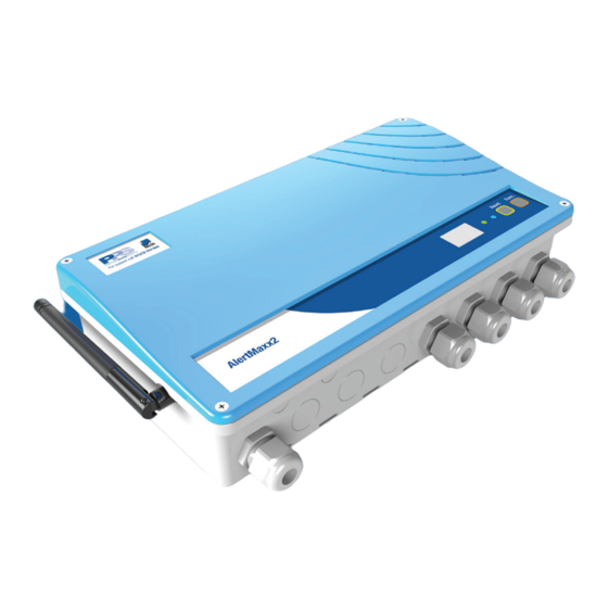
AlertMaxx2 overview The AlertMaxx2 is an intelligent high level alarm, designed to alert home owners when the water level in their pump chamber becomes too high. The unit will also inform home owners when a service is due on their pump station. -
Page 5: Health & Safety
The unit must be positioned where there is sufficient air circulation to the front and base vents. The AlertMaxx2 must not be located further than 10m from the pump/s it is being used in conjunction with. If cable extensions are required, these must be selected in accordance with BS 7671:2008 ‘Requirements for Electrical Installations’. -
Page 6: Wiring Schematic
AlertMaxx2 Wiring schematic The AlertMaxx2 is different from a standard high level alarm as the pump/s require to be fed through the unit. This way of connectivity allows the AlertMaxx2 to collect various different parameters directly from the pumps and when connected via Wi-Fi, this data can be used to intelligently plan maintenance and service schedules to the specific pump station it is connected to (see page 15). -
Page 7: Connecting Mains Power To The Alertmaxx2
AlertMaxx2 Connecting mains power to the AlertMaxx2 Insert 2 large cable glands into the far right hand side of the AlertMaxx2 unit. Using the wiring schematic (figure 1), feed the mains power cable through the relevant cable gland and connect the power cable to the corresponding terminal block on the main PCB (figure 2). -
Page 8: Connecting A Pump To The Alertmaxx2
AlertMaxx2 10.0 Connecting a pump to the AlertMaxx2 Using the remaining cable gland previously installed in section 9.0, feed the pump cable through the gland and connect to the corresponding terminal block on the main PCB (figure 3). Figure 3. Connecting pump... -
Page 9: Installing A Pendant Float Into A Foul Water Chamber
AlertMaxx2 11.0 Installing a pendant float into a foul water chamber Option 1 - Free standing foul pump Using the cable tie provided, attach the float cable to the discharge arm allowing the bottom of the float switch to hang approximately 200mm above the base of the chamber (figure 5). -
Page 10: Connecting A Pendant Float To The Alertmaxx2 Unit
Using a draw cord, pull the float cable through the cable duct on the chamber. Insert a large cable gland into the far left hole of the AlertMaxx2 unit. Pull the float cable through the large cable gland on the AlertMaxx2 unit. -
Page 11: Activating & Testing The Alertmaxx2 Unit
Once the AlertMaxx2 has been installed and fully tested, please apply one of the chamber location stickers, (provided in the box), to the main label of the AlertMaxx2 fascia and one to its relevant fuse spur. This is to signify... -
Page 12: Connecting External Devices
AlertMaxx2 14.0 Connecting external devices The AlertMaxx2 unit has volt free contacts to connect external devices such as an alarm or beacon. When the alarm is activated the relay sends a signal continuously. The volt free relay is designed to accept devices with a maximum load of 0.5A and voltage up to 30V. If external devices fall outside these parameters, the device must be powered by an external power supply. -
Page 13: Error Codes
If you have no PowerMaxx in place, there is the potential of flooding. AlertMaxx2 will run on battery power for 2 days. If you haven’t had a power cut, try to restore power and if the problem persists, contact PPS as soon as possible. -
Page 14: Troubleshooting
AlertMaxx2 18.0 Error codes cont. Meaning All systems OK GREEN slow flash BLUE slow Wi-Fi OK - connected to Gateway OK flash BLUE fast Wi-Fi transmitting flash Wi-Fi in setup mode BLUE fixed BLUE No light Wi-Fi not installed or not functioning 19.0 Troubleshooting... -
Page 15: Hi-Powermaxx Connection
Figure 7. AlertMaxx2 Hi-PowerMaxx connection terminal PLEASE NOTE For wiring the pumps, please refer to the Hi-PowerMaxx manual. The AlertMaxx2 must be installed in series to the Hi-PowerMaxx - this means the AlertMaxx2 must be installed in between the Hi-PowerMaxx & the pump/s. - Page 16 After Sales Service All Delta Membrane pump systems are fitted & can be maintained by our partners, Packaged Pump Systems. With our long-term relationship we ensure that the system selected is fit for your requirements, is delivered on time, professionally installed & offers hassle free on-going operation & maintenance. •...