Carrier 58UVB series Installation, Start-Up, And Operating Instructions Manual
Direct-vent upflow
variable-capacity condensing gas furnace
for sizes 060-120, series 100
Hide thumbs
Also See for 58UVB series:
- Owner's information manual (14 pages) ,
- Owner's manual (16 pages) ,
- Installation, start-up, and operating instructions manual (50 pages)
Table of Contents
Advertisement
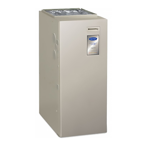
58UVB
Direct---Vent Upflow
Variable---Capacity Condensing Gas Furnace
For Sizes 060---120, Series 100
Installation, Start---Up, and
Operating Instructions
NOTE: Read the entire instruction manual before starting the
installation.
TABLE OF CONTENTS
. . . . . . . . . . . . . . . . . . . . . . . . . . . . . . . . . .
. . . . . . . . . . . . . . . . . . . . . . . . . . . . . . . . . . .
. . . . . . . . . . . . . . . . . . . . . . . . . . . . . . . . . . . . . . . .
Applications
. . . . . . . . . . . . . . . . . . . . . . . . . . . . . . . . . . . . .
. . . . . . . . . . . . . . . . . . . . . . . . . . . . . . . . . . . . . . .
. . . . . . . . . . . . . . . . . . . . . . . . . . . . . . . . . . . . . . . .
. . . . . . . . . . . . . . . . . . . . . . . . . . . . .
. . . . . . . . . . . . . . . . . . . . . . . . . . . . . . . . . .
. . . . . . . . . . . . . . . . . . . . . . . . . . . . . . . . . . . . . . .
. . . . . . . . . . . . . . . . . . . . . . . . . . . . . . .
. . . . . . . . . . . . . . . . . . . . . . . . . . . . .
. . . . . . . . . . . . . . . . . . . . . . . . . . . . . . . . . . . . .
. . . . . . . . . . . . . . . . . . . . . . . . . . . .
. . . . . . . . . . . . . . . . . . . . . . . . . . . . . . . .
. . . . . . . . . . . . . . . . . . . . . . . . . . . . . . . . . . . . . . . .
PAGE
. . . . . . . . . . . . . . . . . . . . . . . .
. . . . . . . . . . . . . . . . . . . . . . . . . .
. . . . . . . . . . . . . . . . . . . . . . . .
. . . . . . . . . . . . . . . . . . . . . . . . . .
. . . . . . . . . . . . . . . . . . . . . . . .
. . . . . . . . . . . . . .
. . . . . . . . . . . . . . . . . . . . . . . . .
. . . . . . . . . . . . . . .
. . .
2
3
4
5
. .
6
6
6
6
6
8
8
10
10
10
10
10
As an ENERGY STAR® Partner,
11
Carrier Corporation has deter-
mined that this product meets
11
the ENERGY STAR® guidelines
for energy efficiency.
12
12
14
18
32
33
. . . . . . . . . . . . . . . . . . . . . . . . . . . . . . . . . . . . .
33
AIRFLOW
UPFLOW
Fig. 1 --- Furnace Orientation
ama
ISO 9001:2000
REGISTERED
. . . . . . . . . . . . . . . . . . . . . . .
. . . . . . . . . . . . . . . . . . .
. . . . . . . . . . . . . . . . . . . . . . . . . . . . . . . . .
. . . . . . . . . . . . . . . . . . . . . . . . . . . .
. . . . . . . . . . . . . . . . . . . . . . . . . . . . . . . . . . . .
. . . . . . . . . . . . . . . . . . . . . . . . . . . .
A06340
CERTIFIED
33
34
35
35
43
48
49
Advertisement
Table of Contents

Related Manuals for Carrier 58UVB series


Summary of Contents for Carrier 58UVB series
-
Page 1: Table Of Contents
........Carrier Corporation has deter-... -
Page 2: Safety Considerations
SAFETY CONSIDERATIONS injury or product and property damage. NOTE is used to highlight suggestions which will result in enhanced installation, CAUTION reliability, or operation. CAUTION FURNACE RELIABILITY HAZARD Improper installation or misapplication of furnace may CUT HAZARD require excessive servicing or cause premature component Failure to follow this caution may result in personal injury. -
Page 3: Dimensional Drawing
" ⁄ " ⁄ " ⁄ " ⁄ AIRFLOW " " ⁄ ⁄ ⁄ " " ⁄ " ⁄ 19" ⁄ " " " ⁄ ⁄ 2-IN. COMBUSTION- " ⁄ AIR CONN OUTLET OUTLET 2-IN. COMBUSTION- AIR CONN -IN. DIA "... - Page 4 332713-201 REV. A (LIT. TOP) A06489 Fig. 3 --- Clearances to Combustibles If this furnace is installed with a direct- -vent (combustion air and Installer Packet Includes: flue) system, a factory accessory termination kit must be installed. Installation, Startup, and Operating Instructions In a direct- -vent system, all air for combustion is taken directly Service and Maintenance Instructions from the outside atmosphere and all flue products are discharged...
-
Page 5: Codes And Standards
Step 2 —General Installation US: NFGC and the NFPA 90B. For copies, contact the National Fire Protection Association Inc., Batterymarch Park, Quincy, MA 02269; or for only the NFGC contact the American Gas Association, 400 N. Capitol, N.W., Washington DC 20001 CANADA: NSCNGPIC. -
Page 6: Electrostatic Discharge (Esd) Precautions
ELECTROSTATIC DISCHARGE (ESD) CAUTION PRECAUTIONS CAUTION MINOR PROPERTY DAMAGE Failure to follow this caution may result in minor property damage. UNIT DAMAGE HAZARD Local codes may require a drain pan under entire furnace Failure to follow this caution may result in damage to unit and condensate trap when a condensing furnace is used in components. - Page 7 FURNACE BLOWER SHELF CONDENSATE DOOR TRAP CONDENSATE TRAP (INSIDE) FURNACE SIDE FIELD DRAIN CONN ALTERNATE DRAIN TUBE LOCATION SIDE VIEW FRONT VIEW CONDENSATE TRAP DRAIN TUBE LOCATION FACTORY-SHIPPED LOCATION ALTERNATE LOCATION 1/ 4 COLLECTOR BOX TO TRAP RELIEF PORT 1/ 2 INDUCER HOUSING DRAIN CONNECTION 5/ 8...
-
Page 8: Location
2. Inducer Housing Drain Tube Attached to the UPPER collector box drain connection is a factory- -installed plug. This plug prevents condensate leakage in a. Remove and discard LOWER (molded) inducer this application. Ensure this plug is secure. housing drain tube which was previously connected to condensate trap. - Page 9 be provided with ample space for servicing and CAUTION cleaning. Always comply with minimum fire protection clearances shown on the furnace clearance- -to- -combustibles label. (See Fig. 3.) UNIT DAMAGE HAZARD This furnace may be located in a confined space without special This gas furnace may be used for construction heat provisions for dilution or ventilation air.
-
Page 10: Low- -Heat Only Installation
Step 3 —Furnace Location Relative to Cooling CAUTION Equipment The cooling coil must be installed parallel with or on downstream UNIT DAMAGE HAZARD side of furnace to avoid condensation in heat exchanger. When Failure to follow this caution may result in minor property installed parallel with a furnace, dampers or other means used to or unit damage. -
Page 11: Air Ducts
2. For each hole, install nut on bolt and then install bolt and Secure ductwork with proper fasteners for type of ductwork used. nut in hole. (Install flat washer if desired.) Seal supply- - and return- -duct connections to furnace with code approved tape or duct sealer. -
Page 12: Bottom Closure Panel
packaged with the cabinet. The Filter/Media cabinet can be used NOTE: Side return- -air openings can be used for return air with the factory- -supplied washable filter or a factory- -specified connections. Install filter(s) as shown in Fig. 14. high- -efficiency disposable filter (see cabinet instructions). For bottom return- -air applications, filter may need to be cut to fit If installing the filter in the furnace blower compartment, some furnace widths. - Page 13 appropriate straps, hangers, etc. Use a minimum of 1 hanger every 6 ft. Joint compound (pipe dope) should be applied sparingly and only to male threads of joints. Pipe dope must be resistant to propane gas. WARNING FIRE OR EXPLOSION HAZARD Failure to follow this warning could result in fire, explosion, personal injury, or death.
-
Page 14: Electrical Connections
TABLE 3—MAXIMUM CAPACITY OF PIPE* WARNING NOMINAL INTERNAL IRON LENGTH OF PIPE (FT) UNIT MAY NOT OPERATE DIAMETER PIPE (IN.) SIZE Failure to follow this caution may result in intermittent (IN.) unit operation. 0.622 Furnace control must be grounded for proper operation 0.824 or control will lock out. - Page 15 FIELD 24-V WIRING FIELD 115-, 208/230-, 460-V WIRING FACTORY 24-V WIRING FACTORY 115-, 208/230-, 460-V WIRING NOTE 5 THERMOSTAT FIVE TERMINALS FIELD-SUPPLIED WIRE DISCONNECT THREE-WIRE HEATING 208/230- OR ONLY 460-V THREE PHASE W/W1 115-V NOTE SINGLE PHASE 208/230-V SINGLE AUXILIARY PHASE 115-V J-BOX...
- Page 16 FACTORY INSTALLED J- -BOX LOCATION SETUP SWITCHES (SW1) Install power entry hole filler plugs (factory- -supplied in loose The furnace control has 8 setup switches that may be set to meet parts bag) in unused power entry holes. (See Fig. 21.) the application requirements.
-
Page 17: Removal Of Existing Furnaces From Common Vent Systems
* * * * * * * * * * * * * * * * * * * * * * * * * * * * * * * * * * * * * * * * * * * * * * * * * * * * * * * * * * * * * * * * * * * * * * * * * * * * * * CONNECTION DIAGRAM TO 115VAC FIELD-DISCONNECT SWITCH SCHEMATIC DIAGRAM... -
Page 18: Combustion- -Air And Vent Pipe Systems
VENTILATED COMBUSTION AIR OPTION CAUTION In a ventilated combustion air option, the vent terminates and discharges the flue products directly to the outdoors similar to a CARBON MONOXIDE POISONING HAZARD direct vent system. See Fig. 35 for required clearances. All air for combustion is piped directly to the furnace from a space that Failure to follow the steps outlined below for each is well ventilated with outdoor air (such as an attic or crawl space) - Page 19 TABLE 5—APPROVED COMBUSTION- -AIR AND VENT PIPE, FITTING AND CEMENT MATERIALS ASTM SOLVENT CEMENT AND SPECIFICATION MATERIAL FITTINGS DESCRIPTION PIPE PRIMERS (MARKED ON MATERIAL) D1527 Pipe — — Schedule--- 40 D1785 Pipe — — Schedule--- 40 D2235 For ABS — —...
- Page 20 NOTE: A 2- -in. diameter pipe must be used within furnace NOTE: Select 1 vent pipe connection and 1 combustion-air pipe connection. casing. Make all pipe diameter transitions outside furnace casing. (See Fig. 24). FLOW COMBUSTION- COMBUSTION- CAUTION VENT UNIT MAY NOT OPERATE VENT Failure to follow this caution may result in incomplete combustion, flame disturbance, or flame sense lockout.
- Page 21 A06497 Fig. 27 --- Attic Termination Attachment of Combustion Air Intake Housing Plug Fitting CAUTION The combustion- -air intake plug fitting must be installed in unused combustion air intake housing. This fitting must be attached by using RTV sealant, or by drilling a 1/8- -in. hole in UNIT DAMAGE HAZARD fitting, using hole in intake housing as a guide.
- Page 22 Combustion Air Termination- -Ventilated Combustion Air WARNING Option Combustion air is piped directly to the burner box on furnace CARBON MONOXIDE POISONING HAZARD using the same materials used to vent the furnace. (See Table 5.) The combustion air pipe is terminated in an attic or crawl space Failure to supply outdoor air via grilles, louvers or vents that is well ventilated with outdoor air and is well isolated from could result in death and/or personal injury.
- Page 23 A06495 Fig. 28 --- Crawlspace Termination A06496 Fig. 29 --- Crawlspace Termination...
- Page 24 COMBUSTION AIR TERMINATION- -DIRECT 5. Install casing hole filler cap (factory- -supplied in loose VENT/2- -PIPE SYSTEM parts bag) in unused vent pipe casing hole. VENT TERMINATION Combustion air pipe must terminate outside the structure with the vent pipe as shown in Fig. 31. Follow the clearance requirements General show in Fig.
- Page 25 COMBUSTION-AIR PIPE VENT PIPE COMBUSTION-AIR PIPE 12 ″ MIN 12 ″ MIN VENT PIPE VERTICAL TO ROOF VERTICAL TO SIDEWALL NOTE: A 12 In. minimum offset pipe section is recommended with short (5 to 8 ft) vent systems. This recommendation is to reduce excessive condensate droplets from exiting the vent pipe.
- Page 26 Roof Termination (Preferred) Vent Maintain 12 in. minimum clearance above highest anticipated snow level maximum of 24 in. above roof. Abandoned masonry used as raceway (per code) 12 in. min. from overhang or roof 6 in. minimum clearance between wall and end of vent pipe. 10 in.
- Page 27 Roof terminations- -Locate assembly through roof to indicated by dashed lines in Fig. 31, install 90_ street appropriate height as shown in Fig. 31 and 32. elbow into 90_ elbow, making a U- -fitting. A 180_ U- -fitting may be used. Sidewall terminations- -Locate assembly...
- Page 28 A05009 Fig. 34 --- Direct Vent Termination Clearance...
- Page 29 A05013 Fig. 35 --- Other than Direct Vent Termination Clearance...
- Page 30 TABLE 8—MAXIMUM ALLOWABLE PIPE LENGTH (FT) UNIT SIZE Termination Pipe Dia NUMBER OF 90_ ELBOWS ALTITUDE (BTUH) Type (IN.)* 2 Pipe or 2--- In. 1--- 1/2 60,000 Concentric 2 Pipe or 2--- In. 1--- 1/2 80,000 Concentric 0 to 2000 2 Pipe or 2--- In.
- Page 31 TABLE 8 — MAXIMUM ALLOWABLE PIPE LENGTH (FT) (CONTINUED) UNIT SIZE Termination Pipe Dia NUMBER OF 90_ ELBOWS ALTITUDE (BTUH) Type (IN.)* 2 Pipe or 2--- In. 1--- 1/2 60,000 Concentric 2 Pipe or 2--- In. 1--- 1/2 80,000 Concentric 6001 to 7000‡...
-
Page 32: Condensate Drain
Step 10 —Condensate Drain CONDENSATE DRAIN PROTECTION Freezing condensate left in condensate trap and drain line may GENERAL cause cracks, and possible water damage may occur. If freeze Condensate trap is shipped installed in the blower shelf. protection is required, use condensate freeze protection accessory Condensate trap can be RELOCATED to the side of the casing. -
Page 33: Start- -Up, Adjustments And Safety Check
2. Thermostat wire connections at terminals R, W/W1, G, and Y/Y2 must be made at 24- -v terminal block on furnace CONDENSATE TRAP control. 3. Natural gas service pressure must not exceed 0.5 psig (14- -in. wc), but must be no less than 0.16 psig (4.5- -in. wc). -
Page 34: Prime Condensate Trap With Water
AIR CONDITIONING AIRFLOW* 060 & 080-14 080-20 & 100 120 MODEL TONS (12,000 BTU/HR) (CFM) MODEL MODEL 1-1/2 525 (600) 700 (800) 2-1/2 875 (1000) 1050 (1200) 3-1/2 1225 (1400) 1400 (1600) 1750 (2000) 2100 (2100) X-INDICATES AN ALLOWABLE SELECTION. * Airflow shown in parentheses is airflow unit that the unit will deliver when setup switch SW1-5 is ON (selects 400 CFM/ton) A/C OR CF AIRFLOW SELECTION CHART BASED ON 350 CFM/TON... -
Page 35: Purge Gas Lines
TABLE 9—FURNACE SETUP SWITCH DESCRIPTION SETUP SWITCH NORMAL SWITCH NAME DESCRIPTION OF USE POSITION Turn ON to retrieve up to 7 stored status codes for troubleshooting SW1---1 Status Code Recovery assistance when R thermostat lead is disconnected. Allows 2--- stage operation with a single stage thermostat. Turn ON when using 2 stage thermostat to allow Low Heat operation when SW1---2 Adaptive Heat Mode... - Page 36 If power is interrupted, the stored history is erased. When this happens, the control CPU will initially select low- -heat for up to 16 minutes and then switch to high- -heat, as long as the thermostat continues to call for heat. Subsequent selection is based on stored history of thermostat cycle times.
- Page 37 2. Igniter Warm- -Up- -At end of the prepurge period, the Hot de- -energizing the humidifier terminal HUM. The inducer Surface Igniter HSI is energized for a 17- -sec igniter motor IDM will remain energized for a 15- -second warm- -up period. post- -purge period.
- Page 38 DHUM to reduce the cooling off- -delay to 5 seconds. (See starts the furnace blower motor BLWM on low- -cooling Fig. 33.) airflow which is the true on- -board CF selection as shown in Fig. 41. The R to Y1- -and- -Y2 circuits start the outdoor 2.
- Page 39 2. High cooling- -When the R to Y/Y2 cicuit is closed, R to G circuit is open, and there is a demand for dehumidifiation, the furnace blower motor BLWM will drop the blower to 65% of high- -cooling airflow for a maximum of 10 minutes each cooling cycle or until the R to G circuit closes or the demand for dehumidification is satisfied.
- Page 40 A00275 Fig. 43 --- Two- -Stage Furnace with Single- -Speed A00277 Air Conditioner Fig. 45 --- Two- -Stage Furnace with Single- -Speed Heat Pump (Dual Fuel) A00276 Fig. 44 --- Two- -Stage Furnace with Two- -Speed Air Conditioner A00278 Fig. 46 --- Two- -Stage Furnace with Two- -Speed Heat Pump (Dual Fuel)
- Page 41 A00281 Fig. 49 --- Two- -Stage Thermostat With Two- -Stage Furnace and Two- -Speed Air Conditioner A00279 Fig. 47 --- Dual Fuel Thermostat with Two- -Stage Furnace and Single- -Speed Heat Pump See note 2 A02348 Fig. 50 --- Single- -Stage Thermostat With Two- -Stage Furnace and Two- -Speed Air Conditioner A00280 Fig.
- Page 42 Notes for Fig. 43- -50: 1. Heat pump MUST have a high pressure switch for dual fuel applications. 2. Refer to outdoor equipment Installation Instructions for additional information and setup procedure. 3. Select the “ZONE” position on the two- -speed heat pump control. 4.
-
Page 43: Adjustments
Step 6 —Adjustments Continuous Blower Speed Selection from Thermostat To select different continuous- -blower speeds from the room SET GAS INPUT RATE thermostat, momentarily turn off the FAN switch or push button Furnace gas input rate on rating plate is for installations at on the room thermostat for 1- -3 seconds after the blower motor altitudes up to 2000 ft. - Page 44 TABLE 11—ORIFICE SIZE* AND MANIFOLD PRESSURES FOR GAS INPUT RATE (TABULATED DATA BASED ON 20,000 BTUH HIGH- -HEAT/13,000 BTUH LOW- -HEAT PER BURNER, DERATED 2%/1,000 FT ABOVE SEA LEVEL) ALTITUDE AVG. GAS SPECIFIC GRAVITY OF NATURAL GAS RANGE HEAT VALUE 0.58 0.60 0.62...
- Page 45 TABLE 11 — ORIFICE SIZE* AND MANIFOLD PRESSURES FOR GAS INPUT RATE (TABULATED DATA BASED ON 20,000 BTUH HIGH- -HEAT/13,000 BTUH LOW- -HEAT PER BURNER, DERATED 2%/1,000 FT ABOVE SEA LEVEL) (CONT) ALTITUDE AVG. GAS SPECIFIC GRAVITY OF NATURAL GAS RANGE HEAT VALUE 0.58...
- Page 46 LOW-FIRE ON/OFF ADJUSTMENT SWITCH ALLEN SCREW (UNDER CAP) HIGH-FIRE ADJUSTMENT ALLEN SCREW INLET (UNDER CAP) PRESSURE BURNER ENCLOSURE REFERENCE PRESSURE TAP MANIFOLD PRESSURE A097386 Fig. 51 --- Redundant Automatic Gas Valve CAUTION UNIT DAMAGE HAZARD Failure to follow this caution may result in reduced furnace life, property damage, personal injury, and death.
- Page 47 NOTE: Clocking gas input rate MUST always be performed CAUTION with the burner box cover INSTALLED. c. Check that gas valve adjustment caps are in place for UNIT DAMAGE HAZARD proper input to be clocked. d. Obtain average heat value (at altitude) from local gas Failure to follow this caution may result in component supplier.
-
Page 48: Check Safety Controls
TABLE 13—GAS RATE CU FT/HR SECONDS SIZE OF TEST DIAL SECONDS SIZE OF TEST DIAL FOR 1 FOR 1 REVOLUTION REVOLUTION cu ft cu ft cu ft cu ft cu ft cu ft 1800 1636 1500 1385 1286 1200 1125 1059 1000 3. -
Page 49: Checklist
CHECKLIST 1. The recommended method of checking this limit control is to gradually block off return air after furnace has been 1. Put away tools and instruments. Clean up debris. operating for a period of at least 5 minutes. 2. Verify flame rollout manual reset switch has continuity. THERMOSTAT SUBBASE 3. - Page 50 Catalog No:58UVB- - 1SI Printed in U.S.A. Edition Date: 09/06 Copyright 2006 Carrier Corp. S 7310 W. Morris St. S Indianapolis, IN 46231 Replaces:New Manufacturer reserves the right to change, at any time, specifications and designs without notice and without obligations.
Need help?
Do you have a question about the 58UVB series and is the answer not in the manual?
Questions and answers