Carrier 58DXT Service And Maintenance Instructions
Weathermaker 8000 two-stage induced-combustion gas furnaces
Hide thumbs
Also See for 58DXT:
- Operating instructions manual (24 pages) ,
- User's information manual (9 pages)
Advertisement
Quick Links
Visit www.carrier.com
Service and Maintenance Instructions
NOTE: Read the entire instruction manual before performing any
service or maintenance.
This symbol → indicates a change since the last issue.
These procedures are for size 60,000 through 120,000 Btuh units.
Index
SAFETY CONSIDERATIONS..................................................1-2
ELECTROSTATIC DISCHARGE (ESD) PRECAUTIONS
PROCEDURE ...........................................................................2
CARE AND MAINTENANCE..................................................2-6
Air Filter Arrangement..........................................................2-3
Blower Motor and Wheel......................................................3-4
Cleaning Heat Exchanger......................................................4-6
Electrical Controls and Wiring.................................................6
Troubleshooting ...................................................................6-10
Unit Wiring Diagram................................................................8
Service Label ............................................................................9
Troubleshooting Guide ...........................................................10
SAFETY CONSIDERATIONS
Installing and servicing heating equipment can be hazardous due to
gas and electrical components. Only trained and qualified person-
nel should install, repair, or service heating equipment.
Untrained personnel can perform basic maintenance functions
such as cleaning and replacing air filters. All other operations must
be performed by trained service personnel. When working on
heating equipment, observe precautions in the literature, tags, and
labels attached to or shipped with the unit and other safety
precautions that may apply.
Follow all safety codes. In the United States, follow all safety
codes including the National Fuel Gas Code NFPA No. 54-
1996/ANSI Z223.1-1996. In Canada, refer to the current edition of
the National Standard of Canada CAN/CGA-B149.1- and .2-M95
Natural Gas and Propane Gas Installation Codes and Amendment
No. 1. Wear safety glasses and work gloves. Have fire extinguisher
available during start-up and adjustment procedures and service
calls.
Recognize safety information. This is the safety-alert symbol
When you see this symbol on the furnace and in instructions or
manuals, be alert to the potential for personal injury.
→
Understand the signal words DANGER, WARNING, CAUTION
and NOTE. These words are used with the safety-alert symbol.
DANGER identifies the most serious hazards which will result in
severe personal injury or death. WARNING signifies a hazard
which could result in personal injury or death. CAUTION is used
to identify unsafe practices which would result in minor personal
injury or product and property damage. NOTE is used to highlight
suggestions which will result in enhanced installation, reliability,
or operation.
Manufacturer reserves the right to discontinue, or change at any time, specifications or designs without notice and without incurring obligations.
Book 1 4
PC 101
Tab 6a 8a
For Sizes 060-120, Series 110 or 120
Catalog No. 535-740
Printed in U.S.A.
WeatherMaker® 8000 Two-Stage
Induced-Combustion Gas Furnaces
Page
Fig. 1—Model 58UXT Horizontal
®
ama
A PP R O VED
R
.
Fig. 3—Model 58UXT Upflow
Form 58D,U-7SM
58DXT, 58UXT
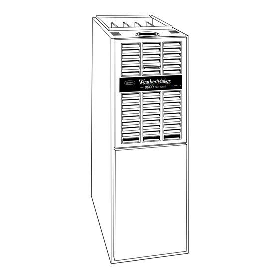
Fig. 2—Model 58DXT
Downflow
REGISTERED
QUALITY SYSTEM
A94085
Pg 1
7-99
Replaces: 58D,U-4SM
A95137
A94086
Advertisement

Related Manuals for Carrier 58DXT


Summary of Contents for Carrier 58DXT
- Page 1 Natural Gas and Propane Gas Installation Codes and Amendment No. 1. Wear safety glasses and work gloves. Have fire extinguisher available during start-up and adjustment procedures and service calls. Fig. 2—Model 58DXT Downflow Recognize safety information. This is the safety-alert symbol A94086 When you see this symbol on the furnace and in instructions or manuals, be alert to the potential for personal injury.
- Page 2 The ability to properly perform maintenance on this equip- Never store anything on, near, or in contact with furnace, such ment requires certain expertise, mechanical skills, tools, and equipment. If you do not possess these, do not attempt to 1. Spray or aerosol cans, rags, brooms, dust mops, vacuum perform any maintenance on this equipment other than those cleaners, or other cleaning tools.
- Page 3 MOUNTING SCREWS AIRFLOW DRAFT SAFEGUARD INSTALLATION SWITCH POSITION OF FILTERS RELIEF RETURN-AIR PRESSURE PLENUM SWITCHES MAIN LIMIT SWITCH MANUAL RESET LIMIT SWITCHES CONTROL FILTER RETAINER ACCESS DOOR WASHABLE FILTER A88486 Fig. 4—Downflow Filter Arrangement A95386 Fig. 5—Model 330JAV Upflow d. Clean filters by spraying tap water through filter from Never operate unit without a filter(s) or with filter access door opposite direction of airflow.
- Page 4 11. Reinstall blower assembly in furnace. FLUE COLLAR 12. Reinstall control and transformer support assembly in furnace. VENT PIPE 13. Reconnect blower leads to furnace control and auxiliary limit ENCLOSURE AUXILIARY switch leads (downflow only). LIMIT SWITCH Refer to furnace wiring diagram, and connect thermostat leads CONTROL if previously disconnected.
- Page 5 insufficient or poor quality combustion air, incorrect size, or (2.) Insert brush end of cable into upper opening of cell damaged manifold orifice(s), improper gas, or a restricted heat and slowly rotate with drill. DO NOT force cable. exchanger. Action must be taken to correct the problem. Gradually insert at least 36 in.
- Page 6 (8.) Reinstall cell outlet plates and screws FIRST; then, ELECTRICAL CONTROLS AND WIRING reinstall cell inlet plates and burner assembly. Care NOTE: There may be more than 1 electrical supply to unit. must be exercised to center burners in cell openings. The electrical ground and polarity for 115-v wiring must be 12.
- Page 7 FIELD 24-V WIRING FIELD 115-, 208/230-, 460-V WIRING FACTORY 24-V WIRING FACTORY 115-V WIRING 1-STAGE THERMOSTAT TERMINALS FIVE FIELD-SUPPLIED WIRE FUSED DISCONNECT TWO-WIRE 208/230- OR HEATING- 460-V ONLY THREE PHASE 208/230-V W/W1 SINGLE PHASE Y/Y2 115-V FUSED JUNCTION DISCONNECT SWITCH CONTROL CONDENSING (WHEN REQUIRED)
-
Page 9: Component Test
SERVICE If status code recall is needed, do not remove power or blower door. Briefly remove and then reconnect one main limit wire to display stored status code. LED CODE STATUS CONTINUOUS OFF - Check for 115VAC at L1 and L2, and 24VAC at SEC1 and SEC2. CONTINUOUS ON - Control has 24VAC power. -
Page 10: Troubleshooting
TROUBLESHOOTING NOTES: WARNING Refer to information label on blower compartment door GUIDE for procedure for use of LED status codes and problem solving suggestions. LED indicator is viewed through window in blower ELECTRICAL SHOCK HAZARD compartment door. If 115-vac power is de-energized or interrupted during a ONLY QUALIFIED AND TRAINED call for heat, the indoor blower will run for 90 sec before SERVICE PERSONNEL SHOULD... - Page 12 [ ] Classroom Service Training A94328 Copyright 1999 CARRIER Corp. • 7310 W. Morris St. • Indianapolis, IN 46231 58du7sm Manufacturer reserves the right to discontinue, or change at any time, specifications or designs without notice and without incurring obligations.
Need help?
Do you have a question about the 58DXT and is the answer not in the manual?
Questions and answers