Vega VEGASWING 51 Operating Instructions Manual
Hide thumbs
Also See for VEGASWING 51:
- Operating instructions manual (36 pages) ,
- Operating instructions manual (36 pages) ,
- Operating instructions manual (36 pages)
Table of Contents
Advertisement
Quick Links
Advertisement
Table of Contents

Related Manuals for Vega VEGASWING 51


Summary of Contents for Vega VEGASWING 51
-
Page 1: Operating Instructions
Operating Instructions VEGASWING 51... -
Page 2: Table Of Contents
3 Product description .......... 8 Configuration ..........8 Principle of operation ......... 9 Storage and transport ........ 9 4 Mounting ............10 Mounting instructions ......10 5 Connecting to power supply......14 Preparing the connection ......14 Wiring plans ..........15 VEGASWING 51... - Page 3 Function test ..........22 Fault rectification ........23 Exchange of the electronics ....24 Repairing the instrument ......26 8 Dismounting ........... 27 Dismounting procedure ......27 Disposal ..........27 Supplement ............28 Technical data ..........28 Dimensions............31 VEGASWING 51...
-
Page 4: About This Document
1.1 Function This operating instructions manual has all the infor- mation you need for quick set-up and safe operation of VEGASWING 51. Please read this manual before you start set-up. 1.2 Target group This operating instructions manual is addressed to trained specialist staff. - Page 5 About this document • List The dot set in front indicates a list with no implied sequence. –> Action This arrow indicates a single action. Sequence Numbers set in front indicate successive steps in a procedure. VEGASWING 51...
-
Page 6: For Your Safety
VEGA personnel. 2.2 Appropriate use VEGASWING 51 is a vibrating level switch for level detection in liquids. 2.3 Warning about misuse Inappropriate or incorrect use of the instrument can give rise to application-specific hazards, e.g. -
Page 7: Ce Conformity
For your safety 2.5 CE conformity VEGASWING 51 is in CE conformity with EMC (89/336/EWG) and NSR (73/23/EWG) and fulfils the Namur recommendations NE 21 and NE 23. Conformity has been judged acc. to the following standards: Electronics version non-contact electronic switch (C): •... -
Page 8: Product Description
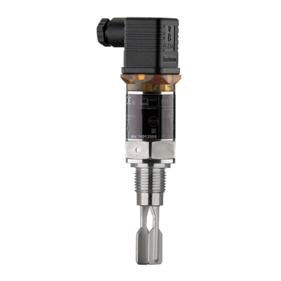
Product description 3 Product description 3.1 Configuration The scope of delivery encompasses: Scope of delivery • VEGASWING 51 level sensor • documentation this operating instructions manual if necessary, various certificates. Fig. 1: VEGASWING 51 VEGASWING 51... -
Page 9: Principle Of Operation
Product description 3.2 Principle of operation VEGASWING 51 vibrating level switches detect lev- Area of application els in almost all liquids. • viscosity 0.1 … 10.000 mPa s • density 0.7 … 2.5 g/cm³. The tuning fork is piezoelectrically energised and... -
Page 10: Mounting
Mounting 4 Mounting 4.1 Mounting instructions In principle, VEGASWING 51 can be mounted in any position. The instrument must be mounted such that the tuning fork is at the height of the required switch- ing point. Transport Do not hold VEGASWING 51 on the tuning fork. - Page 11 The orientation of the tuning fork is marked by a notch on the hexagon of VEGASWING 51. With this you can check the position of the tuning fork when screwing it in.
- Page 12 Make sure that the tuning fork is not subjected to Lateral load strong lateral forces. To assure this, mount VEGASWING 51 at a location in the vessel where no adverse conditions, e.g. caused by stirrers, filling openings etc. can occur. The surfaces of the tuning fork of VEGASWING 51 should be parallel to the product movement/flow.
- Page 13 Rain and condensation water can thus drain off. This applies particularly when mounting outdoors, in humid areas (e.g. by cleaning proc- esses) or on cooled or heated vessels. Fig. 6: Measures to avoid moisture penetration VEGASWING 51...
-
Page 14: Connecting To Power Supply
• Connection only in the complete absence of line Note safety instructions voltage Select connection cable VEGASWING 51 is connected with standard cable. Depending on the plug connection, you have to se- lect the cable diameter so that the seal effect on the cable entry is ensured. -
Page 15: Wiring Plans
For this plug version you can use a standard cable with round cross section. Cable diameter 4.5 … 7 mm. Protection IP 65. This instrument ver- sion is available with transistor electronics (T) and electronics version "Non-contact electronic switch" (C). VEGASWING 51... -
Page 16: Vegaswing
Plug housing Plug insert Profile seal Diodes 10 VEGASWING 51 Valve plug - QuickOn DIN 43650 For this plug version you can use standard cable with round cross section. The inner cables must not be stripped. The plug connects the cables automatically when screwing. - Page 17 PLC inputs. The domestic current is temporarily lowered below 1 mA after switching off the load so that contactors, whose holding current is lower than the constant do- mestic current of the electronics (3 mA), are reliably switched off. VEGASWING 51...
- Page 18 Connecting to power supply Max. Min. Fig. 10: Wiring plan - Non-contact electronic switch with valve plug DIN 43650 Protection earth VEGASWING 51...
- Page 19 Power supply 10 … 55 V DC, I 250 mA (SW E50 T) For connection to binary inputs of a PLC to an input resistance < 100 kOhm. Max. Min. Fig. 11: Wiring plan - Transistor output with valve plug DIN 43650 Equipotential bonding VEGASWING 51...
- Page 20 Connecting to power supply Max. Min. Fig. 12: Wiring plan (housing) - Transistor output with M12x1 plug con- nection Brown White Blue Black VEGASWING 51...
-
Page 21: Set-Up
To select the mode, please note "5 Connecting to power supply". Mode Mode Failure Max. Min. Level Transistor (T) conducts blocks conducts blocks blocks Non-contact switch switch switch switch switch electronic closed open closed open open switch (C) Control lamp green green (flashing) VEGASWING 51... -
Page 22: Maintenance And Fault Rectification
Maintenance and fault rectification 7 Maintenance and fault rectification 7.1 Maintenance In normal operation, the VEGASWING 51 level sensor is completely maintenance-free. 7.2 Function test VEGASWING 51 has an integrated test switch which can be activated magnetically. To test the instrument, proceed as follows: –>... -
Page 23: Fault Rectification
Maintenance and fault rectification If the switching condition of VEGASWING 51 does not change after you have tried it several times with the test magnet, then you have to check the plug connection and the connection cable and test the instrument again. -
Page 24: Exchange Of The Electronics
Proceed as follows to exchange the electronics: 1 Separate VEGASWING 51 from operating voltage 2 Loosen the screw (1) of the valve block (2) with a Phillips screwdriver (loosen the M12x1 plug con- nection by turning the compression nut) 3 Remove valve plug (2) or M12x1 acc. - Page 25 VEGASWING is again ready for use. 1 Screw 2 Valve plug DIN 43650 3 Profile seal 4 Oscillator 5 Rotary switch (16-step) 6 Connection plug 7 Fixing screw 8 Housing Fig. 14: Exchange of electronics VEGASWING 51...
-
Page 26: Repairing The Instrument
Maintenance and fault rectification 7.5 Repairing the instrument If it is necessary to repair VEGASWING 51, please send the instrument to the following address: VEGA Grieshaber KG Repair department Am Hohenstein 113 77761 Schiltach VEGASWING 51... -
Page 27: Dismounting
8.2 Disposal VEGASWING 51 consists of materials which can be recycled by specialised recycling companies. We have purposely designed the electronic modules to be easily separable. Mark the instrument as scrap and dispose of it according to government regula- tions (electronic scrap ordinance, …). -
Page 28: Supplement
Process conditions Process pressure -1 … 64 bar (-100 ... 6400 kPa) Process temperature -40 … +100°C Temperature shock no limitation Density range 0.7 … 2.5 g/cm³ Viscosity 0.1 … 10.000 mPa s Ambient temperature ˚C ˚C Product temperature VEGASWING 51... - Page 29 20 … 253 V DC Output non-contact electronic switch Domestic current requirement approx. 3 mA (via the load circuit) Load current min. 10 mA max. 250 mA Protection Valve plug IP 65 Valve plug QuickOn IP 65 Protection class Overvoltage category VEGASWING 51...
- Page 30 Supplement Mode – Min./Max. max. (overfill protection) min. (dry run protection) changeover through electrical connec tion VEGASWING 51...
-
Page 31: Dimensions
Supplement Dimensions VEGASWING 51 Thread G¾A or ¾ NPT Valve plug DIN 43650 Valve plug DIN 43650 with QuickOn connec- tion M12x1 ~ 36 ~ 59 ø 16 Protective cover ø 31,7 SW32 G 3/4 A ø 21,3 Switching point Thread G1A or 1 NPT Valve plug DIN 43650 Valve plug DIN 43650... - Page 32 VEGA Grieshaber KG Am Hohenstein 113 77761 Schiltach Germany Phone (07836) 50-0 (07836) 50-201 E-Mail info@de.vega.com www.vega.com ISO 9001 All statements concerning scope of delivery, application, use and operating conditions of the sensors and process- ing systems correspond to the information available at the time of printing.
Need help?
Do you have a question about the VEGASWING 51 and is the answer not in the manual?
Questions and answers