
Subscribe to Our Youtube Channel
Related Manuals for Vega VEGAPULS 51P


Summary of Contents for Vega VEGAPULS 51P
- Page 1 Operating Instructions VEGAPULS 51P … 54P (Profibus PA) P R O F I PROCESS FIELD BUS B U S...
-
Page 2: Table Of Contents
Electrical connection .............. 28 4.1 Connection – Connection cable – Screening ....28 4.2 Sensor address ..............31 4.3 Connecting the sensor ............33 4.4 Connecting the external indicating instrument ....34 4.5 Bus configuration ............... 35 VEGAPULS 51P … 54P... -
Page 3: Safety Information
Ex For safety and warranty reasons, any internal approved instruments. work on the instruments, apart from that in- volved in normal installation and electrical con- nection, must be carried out only by qualified VEGA personnel. VEGAPULS 51P … 54P... -
Page 4: Product Description
- the dielectric constant of a substance. system operates as a receiver. Signal run- ning periods of less than one billionth of a second must be processed and the echo image evaluated in a fraction of a second. VEGAPULS 51P … 54P... - Page 5 The high-quality materials can also withstand extreme chemical and physical conditions. The sensors deliver stable, reproducible analogue or digital level signals with reliability and precision. VEGAPULS 51P … 54P...
-
Page 6: Application Features
After the work is done or after a prede- sor or on the Master-Class II adjustment termined time interval, the Token is passed on by the master to the next master. Approvals • CENELEC. ATEX. PTB. FM. CSA. ABS. LRS. GL. LR. FCC. VEGAPULS 51P … 54P... -
Page 7: Adjustment
PC, on an adjustment PC or on the process control computer and can access any VEGA sensor Profibus adjustment structure on the PA level. In the Profibus environment, there are differ-... - Page 8 The adjustment and parameter data can be As a result of this development, three differ- saved at any time on the PC with the adjust- ent adjustment media are available for VEGA ment software and can be protected by Profibus sensors: passwords.
- Page 9 Adjustment of the VEGAPULS radar sensors from process control via a Profibus interface card in the process control computer or in an additional PC. The adjustment software VEGA Visual Operating (VVO) accesses the sensors bidirectionally via the interface (interface card).
- Page 10 Adjustment with SIMATIC PDM adjust- MINICOM ment program With the small (3.2 cm x 6.7 cm) 6-key ad- To adjust all essential functions of the VEGA justment module with display, sensor-relevant sensor with the adjustment station SIMATIC adjustments can be carried out directly on PDM from Siemens, a so-called EDD is re- the sensor.
-
Page 11: Types And Versions
Beside different focusing characteris- lence or products with low tics, each one has special chemical and dielectric constant. physical characteristics. VEGAPULS 51P … 54P... -
Page 12: Survey
– PPS/StSt • – – – – PTFE/PVDF – • – – – PTFE/StSt – • – – – PTFE – – • – – StSt/PTFE – – – • – Hastelloy C22/PTFE – – – • VEGAPULS 51P … 54P... -
Page 13: Mounting And Installation
Hence, those reflections are less critical than those from a flat surface. Round profiles diffuse radar signals Profiles with flat interfering surfaces cause large false signals Cover smooth, flat surfaces with deflectors VEGAPULS 51P … 54P... -
Page 14: Measurement Of Liquids
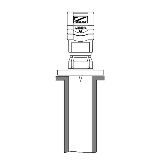
With the adjustment software PACT ware > 10 mm the PC, you can have a look at the echo im- age and optimise the mounting location. Mounting on a dished vessel top VEGAPULS 51P … 54P... - Page 15 The Rod antenna directly on vessel opening top side of the vessel is the reference plane. Reference plane Opening ø 50 mm Mounting directly on flat vessel top Rod antenna directly on vessel opening VEGAPULS 51P … 54P...
-
Page 16: Measurement In Standpipe (Surge Or Bypass Tube)
“ hole Pipe antenna system in the tank Surge pipes which are open at the bottom must extend over the full measuring range (i.e. down to 0% level), as measurement is only possible within the tube. VEGAPULS 51P … 54P... - Page 17 500 mm or more from the max. level. tube bottom to produce a stronger echo than the product (when the bypass tube is nearly empty). By extending the tube downward, some liquid remains at the bottom even when the vessel is completely empty. VEGAPULS 51P … 54P...
- Page 18 • Additional connections to the bypass tube must lie in the same plane as the upper and lower vessel connection (above each other or displaced by 180°). Additional connection in the bypass tube in one plane Optimum connection to the bypass tube VEGAPULS 51P … 54P...
- Page 19 This can be done by welding a plain flange possible in the guide tube. can be welded at the required position on the outside of the guided tube. In both cases, a breather hole must be provided. Flange connections on bypass tubes VEGAPULS 51P … 54P...
- Page 20 Pipe antenna with DN 50. DN 80. DN 100 and DN 150 ø 5...10 In extremely adhesive products, measure- ment in a standpipe is not possible at all. inhomogeneous liquids Openings in a surge pipe for mixing of inhomogene- ous products VEGAPULS 51P … 54P...
- Page 21 The distance to the sensor flange should be at least 500 mm. The seals used should cor- respond to the tube diameter and should be conductive. VEGAPULS 51P … 54P...
- Page 22 DN 100 and DN 150 are equipped with a ~45˚ horn antenna. With these sensors, a plain welded flange can also be used on the sen- sor end instead of a welding neck flange. Min. product level to be measured (0 %) Vessel bottom VEGAPULS 51P … 54P...
- Page 23 1,5…2 Rz ≤ 30 Welding of the welding neck flange 100,8 Deflector Meas. pipe fastening Vessel Quadrant pipe on the bypass tube end bottom ~45˚ Quadrant pipe on the standpipe end VEGAPULS 51P … 54P...
-
Page 24: False Echoes
Intake pipes, e.g. for the mixing of materials - Correct Incorrect with a flat surface directed towards the sen- sor - should be covered with an angled baffle that scatters false echoes. Correct Incorrect Shields Struts Vessel protrusions (intake pipe) VEGAPULS 51P … 54P... - Page 25 Strong product movements Products that cause only light buildup can be Correct Incorrect measured by using a tube with 100 mm nomi- nal width or larger. Light buildup in a tube of this size is no problem. Buildup VEGAPULS 51P … 54P...
-
Page 26: Common Installation Mistakes
Weak measuring signals are generated if the Rod antenna: correct and incorrect socket length sensor is not directly pointed at the product surface. Orient the sensor axis perpendicu- larly to the product surface to achieve opti- mum measuring results. VEGAPULS 51P … 54P... - Page 27 VEGAPULS 54 on the surge pipe: The sensor type plate must be aligned with the rows of holes VEGAPULS 51P … 54P...
-
Page 28: Electrical Connection
In practice, however, an automation network and bus system can only be pro- tected reliably against electromagnetic inter- ference by using screened cable. Acc. to the Profibus specification (IEC 1158-2), screened and twisted cables are prescribed. VEGAPULS 51P … 54P... - Page 29 For sensors with a plastic thread as process sically safe PA connection. VEGA sensors for fitting, the sensor must be grounded via a PA Ex environment are categorically „ia two- ground connection to the exterior ground wire instruments“.
- Page 30 10 mA, so that the number of instruments can be as large as possible. VEGA PA sensors, whether Ex or non-Ex, consume a constant current of 10 mA. Ac- cording to the Profibus specification, this is the minimum participant current.
-
Page 31: Sensor Address
- with the DIP switch block in the sensor 8 7 6 5 4 3 2 1 (hardware addressing). VEGA Profibus sensors are delivered with the address set at 126 (all DIP switches to „ON“). Remember, in a Profibus system there are max. - Page 32 8 7 6 5 4 3 2 1 2 = 2 1 = 1 to „ON. Of course, software addressing is also pos- sible if the switches 7 … 2 are set to „ON“ (address 126). VEGAPULS 51P … 54P...
-
Page 33: Connecting The Sensor
8 7 6 5 4 3 2 1 5 6 7 8 Display Addr. Opening tabs 8 7 6 5 4 3 2 1 5 6 7 8 Display Addr. Pluggable adjustment Tank 1 m (d) module 12.345 MINICOM VEGAPULS 51P … 54P... -
Page 34: Connecting The External Indicating Instrument
(to the sensor) 12.345 Screws DISPLAY (in the lid of the indicating instrument) Power supply and digital meas. signal 8 7 6 5 4 3 2 1 5 6 7 8 Display Addr. Tank 1 m (d) 12.345 VEGAPULS 51P … 54P... -
Page 35: Bus Configuration
Class 2 participants. Like the Master-Class 1 ate without leakage current requirements, so system, they can read out signals, give in- that in Ex environment, up to max. ten VEGA structions and operate in the acyclical mode. sensors can be operated on one segment coupler. - Page 36 Types and Profibus configuration Adresse 1 2…8 Segment coupler Adresse PLC/DCS 21...52 Profibus PA 1 … 32 sensors (Ex: 1 … 10) Master-Class 2 Adresse 10 interface card VEGAPULS 51P … 54P...
- Page 37 Types and Profibus configuration Profibus DP Segment coupler Adresse 53...84 Adresse Adresse Adresse Profibus PA 1 … 32 sensors VEGAPULS 51P … 54P...
-
Page 38: Set-Up
PDM software, an EDD (available ments with the small module faster and more on request from VEGA) is required for each efficiently than with the PC. sensor type. The adjustment instructions for... - Page 39 It is generally advantageous to set the oper- ating range slightly larger (approx. 5 %) than medium the measuring range. Example: Min./max. adjustment: 1.270 … 5.850 m; just- ment adjust operating range to approx. 1.000 … 6.000 m. m(d) (min. adjustment) VEGAPULS 51P … 54P...
- Page 40 (d) corres corres XX.XXX ponds ponds point XXXX XXXX 888.8 Mass (max. adjustment) Now you enter the max. adjustment (upper product distance) (example 100 % and 1.270 m product distance). First you have to enter the VEGAPULS 51P … 54P...
- Page 41 PC and the adjustment program VVO. ence yield a high degree of measurement reliability. 9. Outputs Under the menu "Outputs“ you determine, for example, whether the current output should VEGAPULS 51P … 54P be inverted, or which unit of measurement...
- Page 42 0.0 % 100.0% Adjust Prop. Deci- Min- Unit Max- 100 % ment adjust adjust corres corres m (d) m (d) point ponds at % at % ponds XX.XXX XX.XXX m(d) 888.8 Mass XXXX XXX.X XXX.X XXXX VEGAPULS 51P … 54P...
- Page 43 Simu- lation Prop. Prop. Fail- XXX.X Fast White menu items can be stance change modified with the "+“ or "–“ key mode and saved with the "OK“ key. stance Value VEGAPULS 51P … 54P...
-
Page 44: Diagnostics
10 mm. E036 Sensor software does not run Sensor requires a software update (service). Message appears during a software update. E040 Hardware failure/Electronics defec- Check all connection cables. tive Contact our service department. VEGAPULS 51P … 54P... -
Page 45: Technical Data
Integration time 0 … 999 seconds (adjustable) Adjustment - adjustment software VEGA Visual Operating on Master-Class 2 PC - adjustment module MINICOM in the sensor or in the external indicating instrument (optional) - process adjustment interface PACTware (under which VVO runs as a subprogram) - SIMATIC PDM in conjunction with Electronic Device Description (EDD) Min. - Page 46 30 m -10 mm -20 mm Similar to DIN 16 086, reference conditions acc. to IEC 770, e.g. temperature 15 °C … 35 °C; moisture 45 % … 75 %; pressure 860 mbar … 1060 mbar VEGAPULS 51P … 54P...
- Page 47 (with max. 10% deviation) after a sudden level change. Average emitted power (electromagnetic energy) received by a body per cm² directly in front of the antenna. The received emitted power depends on the antenna version and the distance. VEGAPULS 51P … 54P...
- Page 48 8.3 … 9 kg - DN 150 13.1 … 13.8 kg - ANSI 2“ 4.8 … 5.4 kg - ANSI 3“ 6.6 … 7.1 kg - ANSI 4“ 10.2 … 10.8 kg - ANSI 6“ 14.3 … 15 kg VEGAPULS 51P … 54P...
- Page 49 I-ETS 300-440 Expert opinion No. 0043052-01/SEE, Notified Body No. 0499 EN 61 326: 1997/A1: 1998 (EMC Emission/Susceptibility) EN 61 010 - 1: 1993 (NSR) EN 50 020: 1994 (ATEX) EN 50 018: 1994 EN 50 014: 1997 VEGAPULS 51P … 54P...
-
Page 50: Approvals
- PTB (Physikalisch Technische Bundesanstalt - Physical Technical Approval Authority) - FM (Factory Mutual Research) - ABS (American Bureau of Shipping) - LRS (Lloyds Register of Shipping) - G L (German Lloyd) - CSA (Canadian Standards Association) VEGAPULS 51P … 54P... - Page 51 VEGAPULS 51P … 54P...
-
Page 52: Data Format Of The Output Signal
41 70 00 00 (hex) = 0100 0001 0111 0000 0000 0000 0000 0000 (bin) (130 - 127) Meas. value = (-1) • 2 • (1 + 2 = 1 • 2 • (1 + 0.5 + 0.25 + 0.125) = 1 • 8 • 1.875 = 15.0 VEGAPULS 51P … 54P... -
Page 53: Dimensions
360 (option 510) 100 mm (option 250 mm) VEGAPULS 52 60 mm VEGAPULS 52 170 for standpipe VEGAPULS 52 395 (option 545) 100 mm (option 250 mm) VEGAPULS 53 395 (option 545) 100 mm (option 250 mm) VEGAPULS 51P … 54P... - Page 54 ø36 ø36 ø36 ø36 ø35 ø35 ø35 ø35 ø104 ø138 ø158 ø216 ø125 ø160 ø180 ø240 ø165 ø200 ø220 ø285 DN 50 PN 16 DN 80 PN 16 DN 100 PN 16 DN 150 PN 16 VEGAPULS 51P … 54P...
- Page 55 Exd terminal compartment M20x1,5 M20x1,5 ½" NPT ø76 ø96 ø146 ø241 ø125 ø160 ø180 ø165 ø200 ø240 ø220 ø285 ø355 ø405 DN 50 PN 16 DN 80 PN 16 DN 100 PN 16 DN 150 PN 16 VEGAPULS 51P … 54P...
- Page 56 228.6 25.5 190.5 157.2 19.1 6" 150 psi 279.4 27.0 241.3 215.9 22.4 Adjustment module MINICOM Tank 1 Adjustment module for insertion into sensors m (d) 12.345 or into the external indicating instrument VEGADIS 50 67,5 VEGAPULS 51P … 54P...
-
Page 57: Ce Conformity Declaration
Technical data 7.5 CE conformity declaration VEGAPULS 51P … 54P... - Page 58 VEGAPULS 51P … 54P...
- Page 59 VEGAPULS 51P … 54P...
- Page 60 VEGA Grieshaber KG Am Hohenstein 113 77761 Schiltach Germany Phone (07836) 50-0 (07836) 50-201 E-Mail info@de.vega.com www.vega.com ISO 9001 All statements concerning scope of delivery, application, practical use and operating conditions of the sensors and processing sys- tems correspond to the information available at the time of printing.
Need help?
Do you have a question about the VEGAPULS 51P and is the answer not in the manual?
Questions and answers