Table of Contents
Advertisement
Quick Links
PC, DVI, HDMI, VIDEO, Component INTERFACE CONTROLLER
CONTENTS
Page: 2. Introduction, How to Proceed, Usage Note, Disclaimer
3. System design - Diagram of a suggested system
4. Assembly notes - Important information about system elements
6. Connection & Operation - How to use the controller
10. Connectors, pinouts & jumpers - Essential connection information
29. Appendix I - Supported graphics modes table
45. Warranty, Caution & Limitation of Liability, Trademarks
It is essential that these instructions are read and understood before connecting or
powering up this controller.
Specifications subject to change without notice
© Digital View Ltd - Doc Ver 1.01 : 15 Dec, 2017 (hsp-1920-manual-v101.doc)
HARSH ENVIRONMENT
FOR TFT PANEL
Model: HSP-1920
Part number : 4176001XX-3 or up
INSTRUCTIONS
1 of 47
Page
Advertisement
Table of Contents

Subscribe to Our Youtube Channel
Related Manuals for Digital View HSP-1920


Summary of Contents for Digital View HSP-1920
-
Page 1: Table Of Contents
It is essential that these instructions are read and understood before connecting or powering up this controller. Specifications subject to change without notice 1 of 47 © Digital View Ltd – Doc Ver 1.01 : 15 Dec, 2017 (hsp-1920-manual-v101.doc) Page... - Page 2 Introduction HSP-1920 is the harsh Environment version of the SP-1920. Provides full SP-1920 feature set, plus wide range operating temperature and voltage range; shock and vibration tolerance and conformal coating for extreme environment applications. TFT (active matrix) LCD panels of up to 1920x1200 resolutions.
- Page 3 SYSTEM DESIGN A typical LCD based display system utilizing this controller is likely to comprise the following: Specifications subject to change without notice 3 of 47 © Digital View Ltd – Doc Ver 1.01 : 15 Dec, 2017 (hsp-1920-manual-v101.doc) Page...
- Page 4 18. Alternate composite 1 & composite 2 : Plug the video input cable P/N 426308000-3 on CNV1 connector 19. Component video input : Plug the component video input cable P/N 426000600-3 on CNV2 connector Specifications subject to change without notice 4 of 47 © Digital View Ltd – Doc Ver 1.01 : 15 Dec, 2017 (hsp-1920-manual-v101.doc) Page...
- Page 5 Non-interlaced & interlaced video input is acceptable. • IMPORTANT: Please read the Application Notes section for more information. Specifications subject to change without notice 5 of 47 © Digital View Ltd – Doc Ver 1.01 : 15 Dec, 2017 (hsp-1920-manual-v101.doc) Page...
- Page 6 The settings chosen will be saved for each mode independently. Specifications subject to change without notice 6 of 47 © Digital View Ltd – Doc Ver 1.01 : 15 Dec, 2017 (hsp-1920-manual-v101.doc) Page...
- Page 7 12V / 24VDC power input : Digital 10K Type OSD switch mount uses P/N 416100520-3 or up Digital type Specifications subject to change without notice 7 of 47 © Digital View Ltd – Doc Ver 1.01 : 15 Dec, 2017 (hsp-1920-manual-v101.doc) Page...
- Page 8 * Function in Video mode only ** Function in VGA & Component mode only # Function in VGA mode only Specifications subject to change without notice 8 of 47 © Digital View Ltd – Doc Ver 1.01 : 15 Dec, 2017 (hsp-1920-manual-v101.doc) Page...
- Page 9 Volume [0~100] : Default 50 : Increase/decrease volume level, total: 100 steps Effective on Firmware V1.05.00.00 or up Specifications subject to change without notice 9 of 47 © Digital View Ltd – Doc Ver 1.01 : 15 Dec, 2017 (hsp-1920-manual-v101.doc) Page...
- Page 10 (Matching video cable P/N 426000600-3) CNV4 Alternate VGA input connector Hirose 12-pin, DF11-12DP-2DSA compatible (Matching type : DF11-12DS-2C) Specifications subject to change without notice 10 of 47 © Digital View Ltd – Doc Ver 1.01 : 15 Dec, 2017 (hsp-1920-manual-v101.doc) Page...
- Page 11 Close = composite Cr/Pr input is terminated with 75Ω Panel & function selection See table 2 Panel & function selection See table 3 Specifications subject to change without notice 11 of 47 © Digital View Ltd – Doc Ver 1.01 : 15 Dec, 2017 (hsp-1920-manual-v101.doc) Page...
- Page 12 Because CNA1 pin 1 and CNB1 pin 2 will output 24VDC if input 24VDC via PP2/PP3 or PP5. Specifications subject to change without notice 12 of 47 © Digital View Ltd – Doc Ver 1.01 : 15 Dec, 2017 (hsp-1920-manual-v101.doc) Page...
- Page 13 * Maximum current for 3.3V, 5V = 7A, Maximum current for 12V = 5A, Maximum current for 18V = 3.5A Specifications subject to change without notice 13 of 47 © Digital View Ltd – Doc Ver 1.01 : 15 Dec, 2017 (hsp-1920-manual-v101.doc) Page...
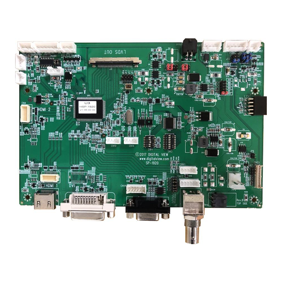
- Page 14 JA3, JA5 & JA6 location on board : (Please pay attention to the jumper settings on JA3, JA5 & JA6 which are red in color) JA6 & JA5 Specifications subject to change without notice 14 of 47 © Digital View Ltd – Doc Ver 1.01 : 15 Dec, 2017 (hsp-1920-manual-v101.doc) Page...
- Page 15 Pos #5 Pos #6 Pos #7 Description WUXGA UXGA SXGA WXGA SVGA WVGA / Others Pos. #8 Reserved Specifications subject to change without notice 15 of 47 © Digital View Ltd – Doc Ver 1.01 : 15 Dec, 2017 (hsp-1920-manual-v101.doc) Page...
- Page 16 1920x1200. * This function is only effective on V1.05.00.00 or later firmware revision. Specifications subject to change without notice 16 of 47 © Digital View Ltd – Doc Ver 1.01 : 15 Dec, 2017 (hsp-1920-manual-v101.doc) Page...
- Page 17 Reserved Ground +12V / +24V Audio board power supply, +12V / +24V No connection No connection Ground Specifications subject to change without notice 17 of 47 © Digital View Ltd – Doc Ver 1.01 : 15 Dec, 2017 (hsp-1920-manual-v101.doc) Page...
- Page 18 The VR for brightness depends on the inverter. The main power load for On/Off is handled by a relay on the controller. Specifications subject to change without notice 18 of 47 © Digital View Ltd – Doc Ver 1.01 : 15 Dec, 2017 (hsp-1920-manual-v101.doc) Page...
- Page 19 IR1 – Infra-Red sensor connector: JST B3B-XH-A compatible (Matching type : XHP-3) SYMBOL DESCRIPTION Ground STDBY_Vcc Stand by voltage IR Data IR data Specifications subject to change without notice 19 of 47 © Digital View Ltd – Doc Ver 1.01 : 15 Dec, 2017 (hsp-1920-manual-v101.doc) Page...
- Page 20 LED1 – Status LED connector: JST 3-way, B3B-XH-A compatible (Mating type : XHP-3 or compatible) DESCRIPTION Green LED pin (anode) LED pin common (cathode) Red LED pin (anode) Specifications subject to change without notice 20 of 47 © Digital View Ltd – Doc Ver 1.01 : 15 Dec, 2017 (hsp-1920-manual-v101.doc) Page...
- Page 21 No connection Digital Ground TMDS Clock+ /RXC TMDS Clock- Green Blue HS_IN Analog horizontal sync Ground No connection Specifications subject to change without notice 21 of 47 © Digital View Ltd – Doc Ver 1.01 : 15 Dec, 2017 (hsp-1920-manual-v101.doc) Page...
- Page 22 PP5 – 12V/24VDC input power supply - Molex 43650-0200 compatible (Mating type : Molex 43645-0200 or compatible) DESCRIPTION +12V / +24VDC Ground Specifications subject to change without notice 22 of 47 © Digital View Ltd – Doc Ver 1.01 : 15 Dec, 2017 (hsp-1920-manual-v101.doc) Page...
-
Page 23: Controller Dimensions
CAUTION: Ensure adequate insulation is provided for all areas of the PCB with special attention to high voltage parts such as the inverter. Specifications subject to change without notice 23 of 47 © Digital View Ltd – Doc Ver 1.01 : 15 Dec, 2017 (hsp-1920-manual-v101.doc) Page... -
Page 24: Application Notes
This can then be matched with function controls connected to CNC1 pins 4 & 3 or 5: see table. CNC1 DESCRIPTION VR A VR WIP Specifications subject to change without notice 24 of 47 © Digital View Ltd – Doc Ver 1.01 : 15 Dec, 2017 (hsp-1920-manual-v101.doc) Page... - Page 25 10 K 4.8 V So this circuit could provide Brightness adjust voltage ranging from 0V to 5V. Specifications subject to change without notice 25 of 47 © Digital View Ltd – Doc Ver 1.01 : 15 Dec, 2017 (hsp-1920-manual-v101.doc) Page...
-
Page 26: Troubleshooting
Generally after common sense issues have been resolved we recommend step by step substitution of known working parts to isolate the problem. Specifications subject to change without notice 26 of 47 © Digital View Ltd – Doc Ver 1.01 : 15 Dec, 2017 (hsp-1920-manual-v101.doc) Page... -
Page 27: Specifications
** Overall suitability for usage in critical applications must be independently tested and verified by the user. Specifications subject to change without notice 27 of 47 © Digital View Ltd – Doc Ver 1.01 : 15 Dec, 2017 (hsp-1920-manual-v101.doc) Page... - Page 28 • technical specifications for the panel from the manufacturer. Re-layout and custom development services are available. • Specifications subject to change without notice 28 of 47 © Digital View Ltd – Doc Ver 1.01 : 15 Dec, 2017 (hsp-1920-manual-v101.doc) Page...
- Page 29 60Hz vertical refresh rate. To support on higher refresh rate over 60Hz, the LCD panel may not support. Specifications subject to change without notice 29 of 47 © Digital View Ltd – Doc Ver 1.01 : 15 Dec, 2017 (hsp-1920-manual-v101.doc) Page...
- Page 30 1680x1050 75Hz 1920x1080 60Hz 1920x1200 60Hz COMPOSITE INPUT PORT : Mode NTSC-M NTSC-J NTSC-4.43 PAL-BDGHI PAL-M PAL-N PAL-60 Specifications subject to change without notice 30 of 47 © Digital View Ltd – Doc Ver 1.01 : 15 Dec, 2017 (hsp-1920-manual-v101.doc) Page...
- Page 31 1440x900 75Hz 1600x1200 60Hz 1600x1200 65Hz 1600x1200 70Hz 1600x1200 75Hz 1680x1050 60Hz 1680x1050 75Hz 1920x1080 60Hz 1920x1200 60Hz Specifications subject to change without notice 31 of 47 © Digital View Ltd – Doc Ver 1.01 : 15 Dec, 2017 (hsp-1920-manual-v101.doc) Page...
-
Page 32: Appendix Ii - Rs-232 Control Protocols
- reference by Input main “o”, ss, Query, Source select(0x98) Range : “0””0”-“6””4” Default : “3””2” Specifications subject to change without notice 32 of 47 © Digital View Ltd – Doc Ver 1.01 : 15 Dec, 2017 (hsp-1920-manual-v101.doc) Page... - Page 33 “A” – 16:9 Set display 0x8e, Set display orientation = “0” – Normal. orientation value/increment/decrement “1” – Vertical Flip. Specifications subject to change without notice 33 of 47 © Digital View Ltd – Doc Ver 1.01 : 15 Dec, 2017 (hsp-1920-manual-v101.doc) Page...
- Page 34 “B” – No function “E” – Aspect/Size “F” – Image Orientation “H” – Brightness “I” – Auto Picture Setup Specifications subject to change without notice 34 of 47 © Digital View Ltd – Doc Ver 1.01 : 15 Dec, 2017 (hsp-1920-manual-v101.doc) Page...
- Page 35 180Hz : “0””0” ~ “6””4” 200Hz : “0””0” ~ “6””4” 220Hz : “0””0” ~ “6””4” 240Hz : “0””0” ~ “6””4” Specifications subject to change without notice 35 of 47 © Digital View Ltd – Doc Ver 1.01 : 15 Dec, 2017 (hsp-1920-manual-v101.doc) Page...
- Page 36 380Hz : "0""0" ~ "3""0" 400Hz : "0""0" ~ "3""1" 420Hz : "0""0" ~ "3""1" 440Hz : "0""0" ~ "3""1" Specifications subject to change without notice 36 of 47 © Digital View Ltd – Doc Ver 1.01 : 15 Dec, 2017 (hsp-1920-manual-v101.doc) Page...
- Page 37 = 2-byte ascii-coded hex number, e.g., parameter value of 0x1e is represented by “1”, “e” | “E” (0x31, 0x6e|0x4e). Please refer to the ASCII to Hex convert table below. Specifications subject to change without notice 37 of 47 © Digital View Ltd – Doc Ver 1.01 : 15 Dec, 2017 (hsp-1920-manual-v101.doc) Page...
- Page 38 0x72 0x53 0x73 0x54 0x74 0x55 0x75 0x56 0x76 0x57 0x77 0x58 0x78 0x59 0x79 0x5A 0x7A Specifications subject to change without notice 38 of 47 © Digital View Ltd – Doc Ver 1.01 : 15 Dec, 2017 (hsp-1920-manual-v101.doc) Page...
-
Page 39: Appendix Iii - Mapping Definition
Appendix III – Mapping definition • Definition of Mapping A : Specifications subject to change without notice 39 of 47 © Digital View Ltd – Doc Ver 1.01 : 15 Dec, 2017 (hsp-1920-manual-v101.doc) Page... - Page 40 • Definition of Mapping B : Specifications subject to change without notice 40 of 47 © Digital View Ltd – Doc Ver 1.01 : 15 Dec, 2017 (hsp-1920-manual-v101.doc) Page...
- Page 41 • Definition of VESA : Specifications subject to change without notice 41 of 47 © Digital View Ltd – Doc Ver 1.01 : 15 Dec, 2017 (hsp-1920-manual-v101.doc) Page...
- Page 42 • Definition of JEIDA : Specifications subject to change without notice 42 of 47 © Digital View Ltd – Doc Ver 1.01 : 15 Dec, 2017 (hsp-1920-manual-v101.doc) Page...
-
Page 43: Appendix Iv - Dv Remote Control Unit Work For Hsp-1920
Composite 2 Press this button in the non OSD menu display mode to select Composite 2 source. Specifications subject to change without notice 43 of 47 © Digital View Ltd – Doc Ver 1.01 : 15 Dec, 2017 (hsp-1920-manual-v101.doc) Page... -
Page 44: Appendix V - Media Failover Function
Appendix V – Media Failover Function HSP-1920 has a capability to play media file via USB that this feature called 'Media failover' option. It means when the video input source is no signal / loss of sync on a designated input, the built-in media player display the video content stored in the USB memory stick on the display automatically. - Page 45 TRADEMARKS The following are trademarks of Digital View Ltd: Digital View • HSP-1920 • Specifications subject to change without notice 45 of 47 © Digital View Ltd – Doc Ver 1.01 : 15 Dec, 2017 (hsp-1920-manual-v101.doc) Page...
-
Page 46: Contact Details
6 How Ming Street Kwun Tong Hong Kong Tel: (852) 2861 3615 Fax: (852) 2520 2987 Sales: hksales@digitalview.com WEBSITE www.digitalview.com Specifications subject to change without notice 46 of 47 © Digital View Ltd – Doc Ver 1.01 : 15 Dec, 2017 (hsp-1920-manual-v101.doc) Page... -
Page 47: Revision History
15 Dec 2017 1.01 Revised Color temperature RS-232 command Revised the supported media format file to "MP4" only. Specifications subject to change without notice 47 of 47 © Digital View Ltd – Doc Ver 1.01 : 15 Dec, 2017 (hsp-1920-manual-v101.doc) Page...
Need help?
Do you have a question about the HSP-1920 and is the answer not in the manual?
Questions and answers