ABB REF 610 Operator's Manual
Feeder protection relay ansi version
Hide thumbs
Also See for REF 610:
- Technical reference manual (177 pages) ,
- Installation manual (35 pages) ,
- Product manual (28 pages)
Table of Contents
Advertisement
Quick Links
Advertisement
Table of Contents

Related Manuals for ABB REF 610


Summary of Contents for ABB REF 610
- Page 1 REF 610 Feeder Protection Relay Operator’s Manual - ANSI Version...
-
Page 3: Table Of Contents
1MRS 755539 Feeder Protection Relay REF 610 Issued: January 30, 2005 Operator’s Manual - ANSI Version Version: Contents 1. Introduction ................5 1.1. About this manual ................5 1.2. The use of the relay ...............5 1.3. Features ..................5 1.4. Warranty ..................7 1.5. - Page 4 REF 610 Feeder Protection Relay 1MRS 755539 Operator’s Manual - ANSI Version 3.3.1. Target LEDs ..............29 3.3.1.1. Green target LED ..........29 3.3.1.2. Yellow target LED ..........29 3.3.1.3. Red target LED ........... 30 3.3.1.4. Programmable target LEDs ........ 30 3.3.2.
-
Page 5: Introduction
1.1. About this manual This manual provides basic information on the protection relay REF 610 and presents detailed instructions on how to use the Human-Machine Interface (HMI) of the relay, also known as the Man-Machine Interface (MMI). In addition to the instructive part, a short chapter on commissioning and maintenance of the relay is included. - Page 6 REF 610 Feeder Protection Relay 1MRS 755539 Operator’s Manual - ANSI Version • Three normally open trip contacts • Two change-over (form c) non-trip contacts and three additional change-over (form c) non-trip contacts on the optional I/O module • Output contact functions freely configurable for desired operation •...
-
Page 7: Warranty
Operator’s Manual - ANSI Version • Battery charge supervision • Continuous self-supervision of electronics and software. • Detachable plug-in unit 1.4. Warranty Please inquire about the terms of warranty of your nearest ABB representative. 1.5. Revision history Version Date Remarks... -
Page 8: Safety Information
REF 610 Feeder Protection Relay 1MRS 755539 Operator’s Manual - ANSI Version Safety information Dangerous voltages can occur on the connectors, even though the auxiliary voltage has been disconnected. National and local electrical safety regulations must always be followed. The device contains components which are sensitive to electrostatic discharge. -
Page 9: Instructions
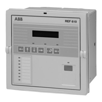
• an HMI push button section with four arrow buttons and buttons for clear/cancel and enter • an optically isolated serial communication port with an target LED. FrvievREF610_b Fig. 3.1.1.-1 Front view of REF 610 1. LCD 2. HMI push button section 3. Programmable target LEDs (red) 4. Target LEDs: •... -
Page 10: Display Modes
When the display is in the idle mode, the name of the feeder will be displayed, which by default is - ABB -. To change the name of the feeder, use SPA parameter M20. Fig. 3.1.2.2.-1 Display in the idle mode When the display is in the view mode, you can only view the settings. -
Page 11: How To Use The Push Buttons
Feeder Protection Relay REF 610 1MRS 755539 Operator’s Manual - ANSI Version Push increase or decrease increase or decrease Fig. 3.1.2.4.-1 Adjusting the display contrast After power pickup of the relay, the factory default value of the display contrast will automatically be restored. -
Page 12: Main Menu
REF 610 Feeder Protection Relay 1MRS 755539 Operator’s Manual - ANSI Version Table 3.1.3-1 Button navigation and editing Resetting latched output contacts in the idle mode for 5 s Acknowledging and resetting targets, latched output contacts and memorized values Resetting thermal level to 0 at power up 3.1.4. - Page 13 Feeder Protection Relay REF 610 1MRS 755539 Operator’s Manual - ANSI Version As soon as you have replaced the default HMI password, the new password will be required for altering parameter values. Once you have given the valid password, the display will remain in the setting mode until returned to the idle mode.
-
Page 14: Spa Password
Changing the SPA password 3.1.8. How to select language REF 610 allows you to choose among several different languages. The default language is English. For the selection of languages, see Fig. 3.1.8.-1. Change the display language as follows: 1. Press an arrow button to access the main menu. -
Page 15: How To Set The Real-Time Clock
Feeder Protection Relay REF 610 1MRS 755539 Operator’s Manual - ANSI Version 3. Press to enter the setting mode and give the password if required. The second line will start to flash indicating that you are allowed to set the language. -
Page 16: How To Reset The Trip Lockout Function
REF 610 Feeder Protection Relay 1MRS 755539 Operator’s Manual - ANSI Version Main Menu Group Menu Parameter Menu MEASUREMENTS RECORDED DATA OPERATION SETTINGS CONFIGURATION CONFIGURATION FUNCTION TEST/DI COMMUNICATION LANGUAGE INFO MEMORY SETTINGS FREQUENCY PASSWORD HMI TIME CONFIGURATION Confirm YY-MM-DD (00-23) TRIP CIRCUIT SUP hh.mm;ss... -
Page 17: How To Switch Between Front And Rear Connection
Feeder Protection Relay REF 610 1MRS 755539 Operator’s Manual - ANSI Version 3.1.11. How to switch between front and rear connection There are two means of serial communication available for the relay: the front connection for SPA bus communication and optional rear communication modules for communication via the SPA bus, IEC 60870-5-103, MODBUS (RTU or ASCII) or DNP 3.0 protocol. -
Page 18: 1.Target Led For Front Communication
3.1.12. How to select the protocol for rear communication When REF 610 is provided with a communication module for the built-in communication protocols, it allows you to choose the communication protocol for rear connection. If REF 610 is equipped with a protocol specific communication module, no communication protocol selections are allowed. -
Page 19: Hmi Operation Levels
Feeder Protection Relay REF 610 1MRS 755539 Operator’s Manual - ANSI Version 3.2. HMI operation levels The HMI menu consists of a user level and a technical level. The user level is used for measuring and monitoring whereas the technical level is used for advanced protection relay setting and can be configured to demand a password. -
Page 20: How To Monitor Recorded Data
REF 610 Feeder Protection Relay 1MRS 755539 Operator’s Manual - ANSI Version Main Menu Group Menu Parameter Menu MEASUREMENTS MEASUREMENTS MEASUREMENTS CT x 0.00 A:x.xx Cancel CT x 0.00 A:x.xx CT x 0.00 A:x.xx RECORDED DATA CT% 0.0 A:x.xx I(unbal)% 0... -
Page 21: Info
Feeder Protection Relay REF 610 1MRS 755539 Operator’s Manual - ANSI Version 5. To return the display to the idle mode, press Main Menu Group Menu Parameter Menu MEASUREMENTS Cancel RECORDED DATA RECORDED RECORDED DATA 1. HH.MM:SS.SSS 1. EVENT 1. YY-MM-DD 1. -
Page 22: Technical Level
REF 610 Feeder Protection Relay 1MRS 755539 Operator’s Manual - ANSI Version Main Menu Parameter Menus MEASUREMENTS RECORDED DATA OPERATION SETTINGS CONFIGURATION INFO INFO REF 610 Cancel xxxxxxxx YYYYMMDD INFO INFO 1MRS118512 A CPU MODULE xxxxxxxx COM. MODULE INFO INFO... - Page 23 Feeder Protection Relay REF 610 1MRS 755539 Operator’s Manual - ANSI Version • with a digital input signal, provided that SGB1...5/4 has been set to 1 in both setting groups (GRP1 and GRP2). • with parameter V150 via the SPA bus.
- Page 24 REF 610 Feeder Protection Relay 1MRS 755539 Operator’s Manual - ANSI Version Main Menu Group Menu Parameter Menu MEASUREMENTS RECORDED DATA OPERATION SETTINGS SETTINGS SETTINGS * GRP1 :x.xx SETTINGS PROTEC. ELEMENTS CT x 0.00 GRP2 :x.xx 51P TDLY s:x.xx 51P Mode...
- Page 25 Feeder Protection Relay REF 610 1MRS 755539 Operator’s Manual - ANSI Version 3. Use to select the desired switchgroup (e.g. SGF2 for display settings) and press 4. Use to select setting group 1 or 2 (GRP1 or GRP2). The active setting group is indicated by an asterisk “*”.
-
Page 26: Configuration
REF 610 Feeder Protection Relay 1MRS 755539 Operator’s Manual - ANSI Version 3.2.2.3. Configuration In general, the parameters found under CONFIGURATION are set only once by the customer, i.e. prior to commissioning of the relay. To alter a parameter: 1. Press an arrow button to access the main menu. - Page 27 Feeder Protection Relay REF 610 1MRS 755539 Operator’s Manual - ANSI Version Main Menu Group Menu Parameter Menu MEASUREMENTS RECORDED DATA OPERATION SETTINGS CONFIGURATION CONFIGURATION CONFIGURATION CONFIGURATION FUNC. TEST DI1 STATUS FUNCTION TEST/ON DI2 STATUS DI STATUS COMMUNICATION LED TEST...
-
Page 28: How To Acknowledge And Reset Targets, Output Contacts And Memorized Values
REF 610 Feeder Protection Relay 1MRS 755539 Operator’s Manual - ANSI Version Main Menu Group Menu Parameter Menu MEASUREMENTS RECORDED DATA OPERATION SETTINGS CONFIGURATION CONFIGURATION FUNCTION TEST/DI COMMUNICATION LANGUAGE INFO MEMORY SETTINGS FREQUENCY CONFIGURATION PASSWORD HMI FREQUENCY TIME FREQUENCY TRIP CIRCUIT SUP... -
Page 29: Target Leds
Feeder Protection Relay REF 610 1MRS 755539 Operator’s Manual - ANSI Version 3.3.1. Target LEDs When a protection element pickups or generates an alarm, the yellow target LED will be lit. When a protection element trips, the yellow target LED will remain lit and the red target LED will be lit. -
Page 30: Red Target Led
REF 610 Feeder Protection Relay 1MRS 755539 Operator’s Manual - ANSI Version The yellow target LED will continue blinking for as long as a protection element remains blocked. The blocking target will disappear with the digital input signal or when the protection element is no longer picked up. -
Page 31: Operation Target Messages
Feeder Protection Relay REF 610 1MRS 755539 Operator’s Manual - ANSI Version 3.3.2.1. Operation target messages When a protection element picks up, the text PICKUP will appear on the display along with the name of the function. Additionally, in case of a latching pickup target, the name of the energizing input(s) which caused the fault will be displayed (except for the thermal protection and phase discontinuity protection). -
Page 32: Disturbance Recorder Target
REF 610 Feeder Protection Relay 1MRS 755539 Operator’s Manual - ANSI Version DEF. TRIP ALARM Fig. 3.3.2.1.-4 Definite Trip-alarm target Latching and non-latching targets A latching operation target message will remain on the display until manually cleared or until replaced by a message of higher priority. However, if the fault is stable and has not disappeared, the operation target message and the LED(s) will not be cleared. - Page 33 Feeder Protection Relay REF 610 1MRS 755539 Operator’s Manual - ANSI Version (ready) is blinking, the fault target cannot be cleared. In case an internal fault disappears, the green target LED will stop blinking and the relay will be returned to the normal service state, but the fault target message will remain on the display until manually cleared (or a motor pickup begins).
- Page 34 REF 610 Feeder Protection Relay 1MRS 755539 Operator’s Manual - ANSI Version May be corrected by formatting to the factory setting. The user-defined values will be set to zero during the internal fault state. Warning In case of a less severe fault (warning), the relay will continue to operate except for those protection functions possibly affected by the fault.
-
Page 35: Detachable Plug-In Unit
• Battery voltage level low - Battery should be replaced - If REF 610 is used without battery, this warning can be disabled by setting non-volatile memory settings to 0 - In case only this warning is active, it will be displayed in text... -
Page 36: Detaching And Installing The Plug-In Unit
REF 610 Feeder Protection Relay 1MRS 755539 Operator’s Manual - ANSI Version Fig. 3.4.1.-1 Checking the order number of the relay 3.4.2. Detaching and installing the plug-in unit Prior to detaching the plug-in unit from the case, the auxiliary voltage must be disconnected. -
Page 37: Inserting And Changing The Battery
Feeder Protection Relay REF 610 1MRS 755539 Operator’s Manual - ANSI Version However, it is highly recomended that all characters in the order number of the substitute plug-in unit, exept for those for indicating a spare part, should match the ones of the case. -
Page 38: Ref 610 Feeder Protection Relay 1Mrs
REF 610 Feeder Protection Relay 1MRS 755539 Operator’s Manual - ANSI Version Battery holder Note! Polarity Battery Fig. 3.4.3.-1 Inserting and changing the battery... -
Page 39: Commissioning And Maintenance
Additionally, correct operation of input and output signals to and from the relay should be verified. REF 610 is a numerical protection relay with functionality implemented in the relay software configuration. Software functionality does not change over time and the relay performs extensive self-supervision during operation. -
Page 40: Maintenance Instructions
REF 610 Feeder Protection Relay 1MRS 755539 Operator’s Manual - ANSI Version Relay commissioning includes: 1. Verifying that the correct application-specific settings have been entered into the relay. This is done by reading the relay settings either via the HMI or serial communication and comparing these to the calculated application-specific settings. -
Page 41: Preventive Parts Replacement
Feeder Protection Relay REF 610 1MRS 755539 Operator’s Manual - ANSI Version 4.2.2. Preventive parts replacement When being used for real-time clock and recorded data functions, the battery should be changed every five years; refer to section Inserting and changing the battery. -
Page 42: Digital Input Test
REF 610 Feeder Protection Relay 1MRS 755539 Operator’s Manual - ANSI Version 7. Press again to return the display to the idle mode. The table below shows the activation order and the corresponding digit flashing when a signal is being tested. -
Page 43: Testing Of Protection Functions
Feeder Protection Relay REF 610 1MRS 755539 Operator’s Manual - ANSI Version 1. Select the programmable LED to target detection of light from the arc detection by setting switch 21 to 1 in the SGL for the chosen LED. It is also possible to route the detected light signal to an output relay, that should be set to be latched. -
Page 44: Testing Of The Ground-Fault Protection
REF 610 Feeder Protection Relay 1MRS 755539 Operator’s Manual - ANSI Version 4.7.2. Testing of the ground-fault protection When calculating the current to be injected into the ground-fault current energizing input, the calculation should be done on the basis of the following: the rated current, 0.2 A, 1 A or 5 A, of the relay energizing input to be tested... -
Page 45: Spare Parts
Feeder Protection Relay REF 610 1MRS 755539 Operator’s Manual - ANSI Version Spare parts 5.1. Plug-in unit The relay’s construction allows a spare part in form of a plug-in unit. The outage time can therefore be reduced to a minimum in case the relay should fail. -
Page 46: Repair
Please contact the manufacturer or the nearest representative for further information on checking, overhaul and recalibration of the relay. When contacting ABB for ordering repair services, give a description of the fault and state the fault code, if applicable. -
Page 47: Ordering Information
Feeder Protection Relay REF 610 1MRS 755539 Operator’s Manual - ANSI Version Ordering information Refer to the Technical Reference Manual. -
Page 48: References
REF 610 Feeder Protection Relay 1MRS 755539 Operator’s Manual - ANSI Version References Other available manuals: • Technical Reference Manual, 1MRS 755535 • Installation Manual, 1MRS 752265-MUM... -
Page 49: Abbreviations
Feeder Protection Relay REF 610 1MRS 755539 Operator’s Manual - ANSI Version Abbreviations ANSI American National Standards Institute ASCII American Standard Code for Information Interchange CBFP Circuit-breaker failure protection Central processing unit Current transformer Digital Input Human-Machine Interface IDMT Inverse definite minimum time characteristic... - Page 50 ABB Inc ABB Oy Distribution Automation Distribution Automation P.O. Box 699 7036 Snowdrift Rd FIN-65101 VAASA Allentown, Pa. 18106 Finland Phone: (610) 395-7333 Tel. +358 10 22 11 Toll Free: (800) 634-6005 Fax. +358 10 224 1094 Fax: (610) 395-1055...
Need help?
Do you have a question about the REF 610 and is the answer not in the manual?
Questions and answers