Table of Contents
Advertisement
Quick Links
Advertisement
Table of Contents

Subscribe to Our Youtube Channel
Related Manuals for Etross GoIP


Summary of Contents for Etross GoIP
-
Page 1: User Manual
User Manual Single Channel GSM Gateway Model: GoIP Release 1.2... -
Page 2: Table Of Contents
GoIP User Manual Contents 1 Introduction ..............3 1.1 Overview ..........................3 1.2 Protocol ..........................4 1.3 Hardware Specification ....................... 5 1.4 Software Specification ......................5 1.5 List of the Package ......................5 1.6 Appearance .......................... 6 2 Installation ..............8 2.1 Connection Diagram ...................... - Page 3 GoIP User Manual 3.5.1 Dial Plan ......................... 30 3.5.1.1 Basic Syntax ....................30 3.5.1.2 Advanced Syntax for Limiting Number Length .......... 31 3.6 SMS Mode ........................32 3.6.1 SMS Dial Mode in SIP ................... 32 3.6.2 SMS Dial Mode in H,323 ................35 3.6.3 SMS Relay Mode (FOR SIP ONLY) .............
-
Page 4: Introduction
1 Introduction 1.1 Overview A VoIP GSM gateway (GoIP) is an IP-based device that enables inbound and outbound VoIP and GSM cellular calls. It is an alternative to a VoIP FXO gateway, especially in area where GSM service is readily available and cheaper for VoIP call termination. Many applications can be evolved from this technology using GSM termination, for examples, distributed call centers, VoIP termination, and cell phone roaming. -
Page 5: Protocol
GoIP User Manual 1.2 Protocol TCP/IP V4 (IP V6 auto adapt) ITU-T H.323 V4 Standard H.2250 V4 Standard H.245 V7 Standard H.235 Standard(MD5,HMAC-SHA1) ITU-T G.711 Alaw/ULaw, G.729A, G.729AB, and G.723.1 Voice Codec RFC1889 Real Time Data Transmission ... -
Page 6: Hardware Specification
DHCP Server Firmware On-line upgrade Caller ID Multiple Language Support Support Multi devices Cooperate Mode 1.5 List of the Package One GoIP gateway main unit One DC4.5V/2000mA power adaptor One Ethernet cable (3M) Release 1.2... -
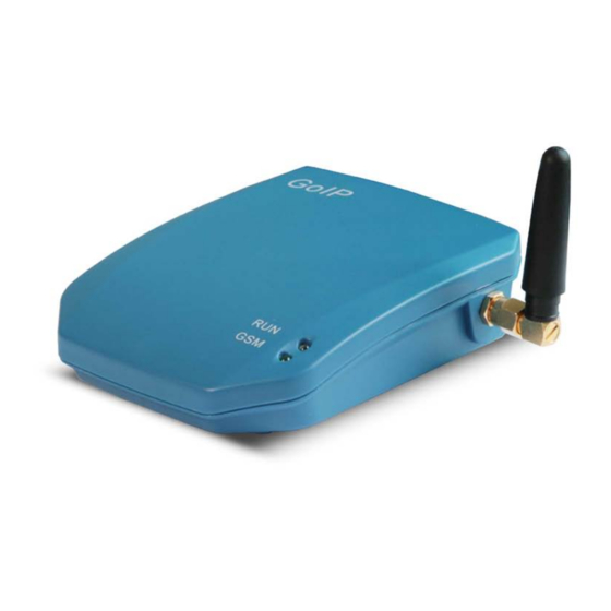
Page 7: Appearance
GoIP User Manual 1.6 Appearance VoIP GSM Gateway (GoIP) – Front View VoIP GSM Gateway (GoIP) – Rear View Release 1.2... - Page 8 2) PC Connect a computer or other network device to this port. 3) POWER (DC4.5V/2000mA) Connect the 4.5V/2000mA adapter provided to this power jack. 4) Reset Press this button to reset the GoIP gateway to factory defaults. Release 1.2...
-
Page 9: Installation
Connect an Ethernet cable the LAN port of the GoIP gateway and the other end to your existing network equipment. Connect an Ethernet cable to the PC port of the GoIP gateway and the other end to a PC or other network device (optional). -
Page 10: Led Indicators
Key word “REBOOT” not case sensitive 1》 Obtain LAN Port IP Address Once the GSM SMS with message content “info” or “INFO” is received, the GoIP sends back a SMS message to the sender with the message content containing the LAN Port IP address. -
Page 11: Configuration Guide
3 Built-in Web Server To configure the GoIP gateway, you must login to its Web server via the LAN or PC port. The LAN port is factory preset to obtain an IP address from the local DHCP host and the PC port is set to the fixed IP address 192.168.8.1. -
Page 12: Web Configuration Menu
If your PC is connected to the GoIP gateway via the LAN port network segment, you need to type the LAN IP address of the GoIP gateway in your Web browser to access the Web server of the GoIP gateway. If not, you should type the PC IP address (192.168.8.1) in the Web browser. -
Page 13: Phone Information
GoIP User Manual 3.2 Status The Status page shown below is the default / home page of the GoIP Web server. It consists of 3 columns status information of the GoIP and they are: a. Phone Information b. Network Information c. -
Page 14: Network Information
GoIP User Manual This field shows terminal’s hardware type. D. Phone Status This field shows the status of line’s connection status. If the connection is successful, this field displays LOGIN; otherwise, it displays LOGOUT. 3.2.2 Network Information A. LAN Port Configuration This field displays the status of the LAN port. -
Page 15: Language
3.3.1 Language Currently GoIP supports English, simplified Chinese and traditional Chinese. Select the language desired and the Web page will be shown in the language selected accordingly. The language can also be selected at the top of the web page. Once selected, the... -
Page 16: Time Zone And Time Server
NTP server (Time Server). The time zone is specified as in GMT ± offset. For example, the Pacific Standard Time is GMT-8, and the Pacific Daylight Time is GMT-7. Note: The GoIP gateway supports CDR and billing information, it is important to set up these two parameters properly. 3.3.3 Auto-Provision The GoIP Gateway supports Auto Provisioning which enables configuration parameters to be set automatically without human intervention. -
Page 17: Gsm Group Mode
For example, the tone definition for a tone of 450Hz with a cadence of 700 ms on and 1000 ms off is 1,0,700,1000,0,0,0,0,450,0,0,0,20,0,0,0 3.3.5 GSM Group Mode The GSM Group mode enables multiple GoIP devices to simulate a multi-channel GSM gateway. Release 1.2... - Page 18 GoIP User Manual In this mode, only one GoIP acts as a Server and the others act as clients of the server and reports its GSM number and status to the server. The number of clients is not restricted. When the server receives a GSM call, it finds an idle client (not engaged in a GSM call) and then forward the call to this client.
-
Page 19: Gsm Caller Id Anonymous
When this parameter is enabled, the GSM Caller ID is not sent; the Caller ID shown at the callee is anonymous. 3.3.8 Auto Reboot When the Auto Reboot box is checked, the GoIP reboots itself automatically at the time specified at the Reboot Time. 3.3.7 Remote Server When this parameter is enabled, the GSM Caller ID is not sent;... -
Page 20: Phone
GoIP User Manual 3.4.1 H.323 Phone For H.323 protocol phone, 2 configuration modes are supported: Single Configuration and Configuration by Group. 3.4.1.1 Single Configuration The Single Configuration supports only one VoIP number to a single H.323 Gatekeeper. A. H.323 Phone Number H.323 phone number: fill the login number (E164) here. -
Page 21: Configuration By Group
If H.235 authentication is required, enable this field and fill in the values as provided. 3.4.1.2 Configuration by Group The “Config by Group” mode allows a user to setup the GoIP gateway to have 4 identities by registering to the same gatekeeper with different phone numbers or to different gatekeepers with different phone numbers or the same phone number, or a combination of both. - Page 22 F) DTMF Signaling 1) DTMF TYPE DTMF signals can be sent over to the called party once a call is established. GoIP gateway supports both Inband and Outband DTMF signal types. For Inband DTMF type, DTMF signals are generated locally at the calling phone and then send to the called party as part of the voice signals.
-
Page 23: Direct Mode
The Direct Mode allows peer-to-peer calls without registering to a gatekeeper. 3.4.2 SIP Phone Set the “Endpoint Type” to SIP phone for connections to SIP servers. GoIP gateway’s SIP configure page as follow: A)Phone Number Enter a SIP phone number. -
Page 24: Advanced Settings
Enter this field for the name to be displayed on the called VoIP party. H) Backup Server The GoIP gateway supports one backup server in case of a main server failure. Once registration to the main server fails, the GoIP gateway will try to register to the backup server. I) Outbound Proxy OutBound proxies are devices that will forward SIP signaling (and frequently RTP media traffic too). - Page 25 GoIP User Manual A) Signaling Port (SIP Local port) The default SIP port is 5060. Change this as required. B) NAT Keep-alive The NAT Keep-alive feature sends a null packet to the SIP proxy periodically in order to keep the NAT open for incoming data traffics.
-
Page 26: Media Setting
E) DTMF Signaling 1) DTMF TYPE DTMF signals can be sent over to the called party once a call is established. GoIP gateway supports both Inband and Outband DTMF signal types. For Inband DTMF type, DTMF signals are generated locally at the calling phone and then send to the called party as part of the voice signals. - Page 27 This parameter specifies the range of the RTP (Real Time Protocol) ports used by the GoIP gateway. If your network limits the usable port range, this parameter may need to be modified. Please consult your network administrator for more information.
-
Page 28: Codec Preference
3.4.5 NAT Traversal 3.4.5.1 Signaling NAT Traversal Signaling NAT traversal may be required if the GoIP gateway is put behind a NAT (or multiple NATs). Depending on your network environment and SIP server capabilities, this feature may or may not be turn on. -
Page 29: Media Nat Traversal
GoIP User Manual 3.4.5.2 Media NAT Traversal Similar to Signaling NAT Traversal, this feature allows media packets (RTP) to be routed properly in various network environments. A) None Select None to disable this feature. B) STUN (RFC 3489 ) STUN (Simple Traversal of UDP (User Datagram Protocol) through NATs... -
Page 30: Call Divert
Forward Password This field sets the password protection for using the GSM connection. If a password is entered, the GoIP gateway will generate an indication tone and wait for the call to dial the Dial Plan to PSTN This field sets the password protection for using the GSM connection. If a password is... -
Page 31: Dial Plan
GoIP gateway will generate an indication tone after answering an incoming call. The caller is then ready to dial the password. Once the password is correctly entered, the GoIP gateway generates a VoIP dial tone and waits for the caller to dial a VoIP number. Dial Plan to VoIP This field sets the password protection for using the GSM connection. -
Page 32: Advanced Syntax For Limiting Number Length
GoIP User Manual example, A = [2-8] means that the number dialed with the leading digit being in the range from 2 to 8 is a match and the corresponding action is executed. Examples: 1. Dial Plan: "0:|:+0755". a. Input: "02083185711" -> Output: “02083185711";... -
Page 33: Sms Mode
The caller initiates a call by sending a SMS message to the service provider via the GoIP. Once the GoIP receives the SMS, it will initiates a call to the SIP Server (Service Provider) based on the SMS contents. This is not an actual voice call that will be answered. Once the Service Provider receives the call information via the SIP call, it then connects the GSM Caller and the Callee (the number specified in the SMS content) together. - Page 34 MESSAGE, INFO, SUBSCRIBE Content-Type: application/sdp Content-Length: 2. Mode 2 GoIP uses its SIP number as the caller ID to call the number specified in the message content. For example: GSM Caller (+86) 13800000000 sends a SMS to the GoIP with the message “8675588228822”.
- Page 35 GoIP User Manual GoIP uses the GSM Caller ID and the SMS message content to form a new SIP number. It will then call this number. This SIP number is in the format shown below. SIP number = SMS Message content + “*” + GSM Caller ID...
-
Page 36: Sms Dial Mode In H,323
Similarly, SMD Dial Mode also works in H.323 Protocol in order to support Call Back Service. The user still sends a SMS message to the GoIP to initiate the call back. The H.323 protocol for initiating a call after receiving a Call Back SMS message Call Back has 3 different formats as described below. - Page 37 GoIP User Manual GSM Caller (+86) 13800000000 sends a SMS to the GoIP with the message “8675588228822”. The GoIP uses its own H.323 ID to call the number 8675588228822. The H.323 protocol command involved is: Send RAS Message: admissionRequest admissionRequest {...
- Page 38 = FALSE 3. Mode 3 (Currently not supported) GoIP uses the GSM Caller ID and the SMS message content to form a new SIP number. It will then call this number. This SIP number is in the format shown below.
-
Page 39: Sms Relay Mode (For Sip Only)
GSM SMS is sent from 8613682626865. b) GSM SMS content is 075583185700. c) SMS Forward Number is set to 3999 d) GoIP creates a new message containing the GSM Caller ID and the GSM SMS received 8613682626865 075583185700 e) The SIP Message sent from GoIP to the SIP Server is:... - Page 40 8613682626865 075583185700 Relay a SIP SMS to a GSM Phone Here is an example of the SIP SMS sent to the GoIP a) SIP number or extension of sending SMS is 3999 b) GoIP SIP number is 20001 c) Designated GSM number for the SMS is...
-
Page 41: Relay Incoming Caller Id (Gsm To Voip Call)
3.7 Relay Incoming Caller ID (GSM to VoIP Call) For SIP mode, the GoIP allows the incoming caller ID from a GSM Call to be transferred to a VoIP terminal. This parameter is called CID Forward Mode and it can be accessed under the Call Divert Page as shown below. -
Page 42: Gain Settings
GoIP User Manual For H.323 mode, this feature is currently not supported and it will be supported in future firmware releases. 3.8 Gain Settings… A hidden webpage is provided to set the receiving and transmit gains of VoIP Channel. The URL link is: http://xxx.xxx.xxx.xxx/default/en_US/gain.html... -
Page 43: Network Configuration
Three LAN Port modes are supported: DHCP, Static IP, PPPoE. 1) DHCP Choose DHCP if a local DHCP host is available. This allows the GoIP gateway to obtain network information (IP Address, Subnet Mask, Default Route, Primary DNS, Secondary DNS, and other DHCP options) from the DHCP host. -
Page 44: Pc Port Configurations
3.9.2 PC port configurations The PC Port allows addition network devices to be attached behind the GoIP Gateway. It offers both Bridge and Static IP modes to meet your network topology. It is factory preset to the Static IP mode with the IP address 192.168.8.1. -
Page 45: Save Configuration
1) Bridge Mode Select Bridge mode if your network topology requires the network devices (PC or others) to be in the same network segment as the GoIP gateway. In this case, the GoIP gateway functions as an Ethernet switch. 2) Static IP Mode (Default Setting) Select Static IP mode for a new network segment for the network devices behind the GoIP gateway. -
Page 46: Discard Changes
GoIP User Manual 3.11 Discard Changes To discard all changes made, click on the Discard Changes tab. 3.12 Tools Menu Select the Tools to access the following functions: Online Upgrade, Change Password, Reset Config, and Reboot. 3.12.1 Online Upgrade To perform a firmware upgrade, select the Online Upgrade tab to access the page below. -
Page 47: Change Password
“admin”. This user name allows full access to all configuration settings available. 3.12.3 Reset Configuration Click on the Reset Config tab to reset the GoIP gateway to its factory default settings. 3.12.4 Reboot the Device Click on the Reboot tab to reboot the GoIP gateway. The web page is then not accessible until the device completes the reboot process. -
Page 48: Hardware Specifications
GoIP User Manual 4 Hardware Specifications Item Description Remark ARM9E 133MHz VPDSP101 95MHz FLASH Power Supply DC4.5V/2000mA +-10% Input AC100V to AC240V Huawei GSM Module - GSM 850 MHz/GSM 900 MHz GSM Module Simcom GSM Module: GSM Default: 900 / 1800 MHz... -
Page 49: Useful Factory Default Settings
GoIP User Manual 5 Useful Factory Default Settings Parameter Defaults DHCP Client mode Ethernet Fixed IP:192.168.8.1 Admin mode: admin/admin Login ID / Password User mode User/1234 Time Zone GMT+8 Release 1.2...
Need help?
Do you have a question about the GoIP and is the answer not in the manual?
Questions and answers