Viessmann VITOTROL 200 RF Installation And Service Instructions Manual
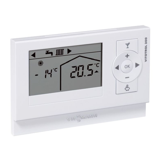
Wireless remote control for one heating circuit
Hide thumbs
Also See for VITOTROL 200 RF:
- Installation and service instructions manual (21 pages) ,
- Operating instructions manual (20 pages) ,
- Installation instructions for contractors (4 pages)

Related Manuals for Viessmann VITOTROL 200 RF


Summary of Contents for Viessmann VITOTROL 200 RF
- Page 1 VIESMANN Installation and service instructions for contractors Vitotrol 200 RF Wireless remote control for one heating circuit For applicability, see the last page VITOTROL 200 RF Please keep safe. 5602 119 GB 3/2011...
-
Page 2: Safety Instructions
Safety instructions Safety instructions Please follow these safety instructions closely to prevent accidents and mate- rial losses. Safety instructions explained ■ all current safety regulations as defined by DIN, EN, DVGW, TRGI, Danger TRF, VDE and all locally applicable This symbol warns against the standards, risk of injury. - Page 3 ■ When using gas as fuel, also close the For replacements, use only orig- main gas shut-off valve and safeguard inal spare parts from Viessmann against unauthorised reopening. or those which are approved by ■ Isolate the system from the power sup- Viessmann.
-
Page 4: Table Of Contents
Installation instructions Installation sequence Usage information....................Installation location....................Commissioning the Vitotrol 200 RF..............Checking the transmission and reception quality at the installation site....Fitting the wall mounting base................Inserting and removing the remote control............Changing the heating circuit assignment following commissioning..... 10 Changing the display contrast................ -
Page 5: Installation Sequence
Installation sequence Usage information The Vitotrol 200 RF can be connected to Up to three Vitotrol 200 RF can be log- a Vitotronic control unit only in conjunc- ged on at the same time at the wireless tion with the associated wireless base base station of a Vitotronic control unit. -
Page 6: Commissioning The Vitotrol 200 Rf
■ The control unit to which the wireless base station is connected must be switched on. 1. Site all the Vitotrol 200 RF near the wireless base station. 2. Insert batteries (LR 6/AA, included in the standard delivery) into the remote control unit. - Page 7 Installation sequence Commissioning the Vitotrol 200 RF (cont.) 3. Press A on the wireless base sta- tion: ■ Operation without wireless repeat- ers: for 4 s. The green LED on the wireless base station flashes slowly. ■ Operation with wireless repeaters: for 8 s.
-
Page 8: Checking The Transmission And Reception Quality At The Installation Site
■ Heating circuit 3 – "H 3" to 5 min). Checking the transmission and reception quality at the instal- lation site 1. Position the Vitotrol 200 RF at its 4. If the transmission and reception intended installation site. quality is inadequate, either select a different installation site and repeat 2. -
Page 9: Fitting The Wall Mounting Base
Installation sequence Fitting the wall mounting base Inserting and removing the remote control Insertion... -
Page 10: Changing The Heating Circuit Assignment Following Commissioning
Installation sequence Inserting and removing the remote control (cont.) Removal Changing the heating circuit assignment following commis- sioning 1. Press 4. OK to confirm. simultaneously at the The operating state of the heating remote control for approx. 4 s. system is transferred. The display segments rotate (for up 2. -
Page 11: Changing The Display Contrast
Installation sequence Changing the heating circuit assignment… (cont.) Installation and service instruc- tions or service instructions of the control unit Changing the display contrast 1. Press simultaneously at the remote control for approx. 4 s. 2. With / select "C4". 3. -
Page 12: Troubleshooting
Troubleshooting Fault display symbol flashes on the display if a fault has occurred. For troubleshooting, see the installation and service instruc- tions of the relevant control unit. If the display shows "_ _ _ _ " and , then the wireless connection has been lost or has not yet built. -
Page 13: Specification
Specification Specification Power supply 2 batteries LR 6/AA/ Mignon 3 V–, 2600 mAh Battery service life approx. 2 years Radio frequency 868.3 MHz Safety category IP rating IP 30 Permissible ambient temperature ■ during operation 0 to +40 °C −20 to +65 °C ■... -
Page 14: Parts List
Parts list Parts list When ordering spare parts Parts not shown Quote part no. 7441652 and the position 080 Installation and service instructions no. of the part (as per this parts list). 081 Operating instructions Obtain standard parts from your local supplier. - Page 16 Applicability Serial No.: 7441652 Viessmann Werke GmbH&Co KG Viessmann Limited D-35107 Allendorf Hortonwood 30, Telford Telephone: +49 6452 70-0 Shropshire, TF1 7YP, GB Fax: +49 6452 70-2780 Telephone: +44 1952 675000 www.viessmann.com Fax: +44 1952 675040 E-mail: info-uk@viessmann.com...
Need help?
Do you have a question about the VITOTROL 200 RF and is the answer not in the manual?
Questions and answers