Table of Contents
Advertisement
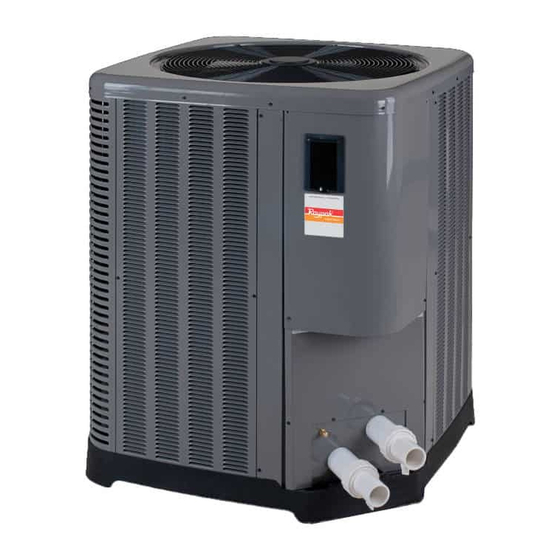
INSTALLATION AND
OPERATION MANUAL
Heat Pump
Pool & Spa
Heater
Model Series
2450, 3450, 4450,
5450, 6450,
6450PD, 6450HC,
8450 & 8450HC
FOR YOUR SAFETY: Do not store or use gasoline or other flammable vapors and
liquids or other combustible materials in the vicinity of this or any other appliance.
To do so may result in an explosion or fire.
NOTE: The instructions in this manual are for the use of qualified individuals specially trained and experienced
in the installation and maintenance of this type of equipment and related system components. Installation and
service personnel are required by some states to be licensed. Persons not qualified shall not attempt to install,
service, or maintain this equipment.
This manual should be maintained in legible condition and kept adjacent to the heat pump pool heater or in a
safe place for future use.
Catalog No. 6000.56C
Effective: 01-12-18
Replaces: 11-20-17
92-105917-01-04
Advertisement
Table of Contents


Need help?
Do you have a question about the 3450 and is the answer not in the manual?
Questions and answers
What minimum distance must be provided for a privacy screen to the heat pump pool heater?