
Related Manuals for Comtrol Rocket linx ES8508


Summary of Contents for Comtrol Rocket linx ES8508
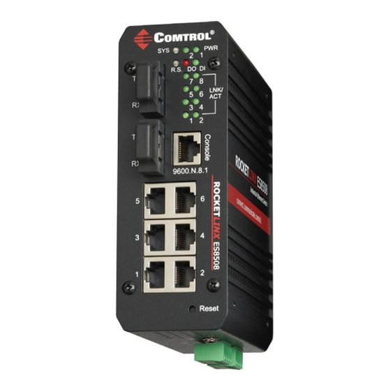
- Page 1 ROCKETLINX ES8508 ES8508 | ES8508F | ES8508-XT | ES8508F-XT QUICK INSTALLATION GUIDE 2000577 Rev B | Release Date - September, 2013...
-
Page 2: Installation Overview
The different ES8508 models are simply referred to as the ES8508 unless there is model specific information. See the Comtrol website for complete product specifications. INSTALLATION OVERVIEW You can use the following overview to install the ES8508. If you need... - Page 3 Power should be disconnected from the power supply before connecting it to the switch. Otherwise, your screwdriver blade can inadvertently short your terminal connections to the grounded enclosure. Wiring the Alarm Relay Output The alarm relay output or digital output (DO) contacts are on the terminal block connector on the bottom of the ES8508.
- Page 4 Wiring the Digital Input The digital input (DI) contacts are on the terminal block connector on the bottom of the ES8508. The contacts accept one external DC type signal input and can be configured to send alert message through Ethernet when the signal is changed.
- Page 5 from connected devices to negotiate the link speed and duplex mode. Auto MDI/MDIX allows users to connect another switch, hub, or workstation without changing straight through or crossover cable. Link/Act LEDs are lit to indicate traffic and link status, see the LEDs subsection for more information.
-
Page 6: Programming The Ip Address
Start PortVision DX. PortVision DX can be started from Start --> All Programs --> Comtrol --> PortVision DX. Click the Scan button. Select the Comtrol product families that you want to locate and click the Scan button. Right-click the ES8508 in the Device List pane (lower) that you want to configure and click Properties. -
Page 7: Led Indicators
Optionally, select the appropriate Network Topology, which is an informational field. 10. Click the Apply Changes button. 11. Click Close to return to the main screen. 12. You are now ready to configure the ES8508 features. LED INDICATORS You can also view the LEDs for the ES8508 through the web interface using the Device Front Panel page. -
Page 8: Comtrol Customer Service
You can use the help system or the RocketLinx ES8508 Series User Guide for information about configuring RocketLinx ES8508 features. COMTROL CUSTOMER SERVICE You can use one of the following methods to contact Comtrol. Contact Method Web Address or Phone Number Support http://www.comtrol.com/support...