Advertisement
Table of Contents
- 1 Table of Contents
- 2 Important Safety Advice
- 3 Product Information
- 4 Installation
- 5 High Voltage Connections
- 6 Panel Display, Switches and Cuicuit Breaker
- 7 Technical Information
- 8 Heating Output Rates by Stages
- 9 Commisioning Checklist
- 10 Khe Series Electrical Furnace
- 11 Wiring Diagram - Psc & Ecotech Rescue Motors
- 12 Exploded View Khe
- Download this manual
Installation, Operation and Service
Manual
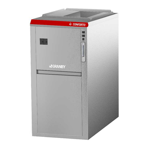
Conforto
Electric
Furnace
KHE 10 TO 27kW
INSTALLATIONS MUST MEET ALL LOCAL AND FEDERAL CODES THAT MAY
DIFFER FROM THIS MANUAL
Please read the complete manual before beginning installation. This
manual must be kept with the furnace for future reference. For
maintenance or question, please refer to your installer – contractor
directly.
02-13-2018
G2018-A1 Rev. A
Advertisement
Table of Contents

Subscribe to Our Youtube Channel
Related Manuals for Granby KHE-00-G010-03


Summary of Contents for Granby KHE-00-G010-03
- Page 1 Installation, Operation and Service Manual Conforto Electric Furnace KHE 10 TO 27kW INSTALLATIONS MUST MEET ALL LOCAL AND FEDERAL CODES THAT MAY DIFFER FROM THIS MANUAL Please read the complete manual before beginning installation. This manual must be kept with the furnace for future reference. For maintenance or question, please refer to your installer –...
-
Page 2: Table Of Contents
TABLE OF CONTENTS IMPORTANT SAFETY ADVICE PRODUCT INFORMATION INSTALLATION HIGH VOLTAGE CONNECTIONS PANEL DISPLAY, SWITCHES AND CUICUIT BREAKER TECHNICAL INFORMATION HEATING OUTPUT RATES BY STAGES COMMISIONING CHECKLIST KHE SERIES ELECTRICAL FURNACE WIRING DIAGRAM – PSC & ECOTECH RESCUE MOTORS EXPLODED VIEW KHE... -
Page 3: Important Safety Advice
IMPORTANT SAFETY ADVICE Please read and understand this manual before installing, operating or servicing the furnace. To ensure you have a clear understanding of the operation of the unit please take the time to read the IMPORTANT SAFETY ADVICE section of this manual. WARNING –... -
Page 4: Installation
INSTALLATION OVERVIEW Install this appliance in accordance with these instructions and all national and local building/safety codes and requirements. Only connect this furnace to a duct system with a maximum static pressure of 0.60” W.C. Static pressures in excess will result in reduced air flow and potential elevated discharge air temperatures during heating cycles and reduced discharge air temperatures during cooling cycles. - Page 5 Due to the hazardous nature of electrical and mechanical requirements only trained and qualified personnel should install and service heating and cooling equipment. WARNING It is important to check airflow and make sure that the furnace does not operate above the temperature rise specified in the specifications, Section 6.
-
Page 6: High Voltage Connections
Clearances to combustible materials The Furnace - The furnace is approved for zero clearance to combustible materials regardless of the heating capacity. It is recommended that 24” (60cm) be provided at the front of the furnace for clear access for servicing. Supply Air Ducts - Supply ducts for furnaces with a heating capacity up to and including 20kW may be installed with 0’’... -
Page 7: Panel Display, Switches And Cuicuit Breaker
Low voltage connections Contained within the control enclosure is the low voltage transformer. This is 240Vac primary with 24Vac secondary, 40VA class 2 transformer. It provides power to the furnace controller, thermostat, A/C or heat pump compressor relay and 24Vac external devices. Always ensure that the load imposed by external devices does not exceed 40 VA (1A). - Page 8 Operation options DIP switches A, B, C These switches are used to select the correct kW/H output of the furnace. See chart below. BTU SETTING TABLE (DIP OPTION SWITCHES) 10KW 15KW 18KW 20KW 23KW 27KW Operation option DIP switch D - Quiet Comfort Feature When the Quiet Comfort Feature has been activated at DIP switch D and the continuous circulation fan switch is in the ON position, the LED light on the front of the furnace will flash AMBER.
- Page 9 ComfortMAX Mode The ComfortMax exclusive feature is designed to provide automatic system kW/H output sizing when operated by a single stage thermostat. When using a 2 stages thermostat, the 2nd stage of the thermostat heat call takes priority. To activate The ComfortMax feature, remove the jumper wire across W1 and W2 at the thermostat terminals on the furnace control board and set the ComfortMax switch on the furnace to ON.
-
Page 10: Technical Information
TECHNICAL INFORMATION GENERAL INFORMATION DIMENSIONS (WIDTH X DEPTH X HEIGHT) 20“ X 21“ X 36“ WARM AIR PLENUM 15“ X 18“ RETURN AIR PLENUM 18 1/2“ X 18 1/2“ AIR FILTER – 1 SUPPLIED 20“ X 20“X 1“ SHIPPING WEIGHT 48 KG (105lbs.) 10 to 23kW 27kW... -
Page 11: Heating Output Rates By Stages
Static Pressure at 0.2’’ WC ∕ 0.5’’ WC Blower PSC 1∕3 HP PSC 3∕4 HP Blower ECM 1∕2 HP ECM 3∕4 HP speed speed 0.20’’WC 0.50’’WC 0.20’’WC 0.50’’WC 0.20’’WC 0.50’’WC 0.20’’WC 0.50’’WC HIGH 1237 1150 2120 2030 HIGH 1300 1230 2000 1910 M-HIGH... -
Page 12: Khe Series Electrical Furnace
2) Place a jumper across R, Y/Y2 & G, fan starts on Cool speed and A/C starts. 3) Remove jumper, fan cycles down and A/C stops. 4) Power furnace down, connect thermostat, turn power to furnace on. KHE SERIES ELECTRIC FURNACE... -
Page 14: Exploded View Khe
EXPLODED VIEW KHE ITEM NO PART NUMBER DESCRIPTION 6EF-FE-04KW-00, 4KW ELEMENT C/W #10 STUD CON & NUT 6EF-FE-05KW-00 5KW ELEMENT C/W #10 STUD CON & NUT 4SW-00-RA90-10 ROCKER SWITCH SP/ST 15AMP MARKED ON/OFF 4SW-00-RA90-10 ROCKER SWITCH SP/ST 15AMP MARKED ON/OFF 6EF-CI-BRKS-00 16A THERMAL CIRCUIT BREAKER T9-611P-16A 6EF-RY-DC24-00... - Page 15 GRANBY FURNACES INC. PO Box 637 12118 Hwy 209 Parrsboro, Nova Scotia, Canada B0M 1S0 www.granbyindustries.com Thank you for choosing Granby...
Need help?
Do you have a question about the KHE-00-G010-03 and is the answer not in the manual?
Questions and answers