Table of Contents
Advertisement
Quick Links
Installation, Operation and
KHM
80% + EFFICIENCY
GAS FIRED CATEGORY I HI-BOY FURNACE
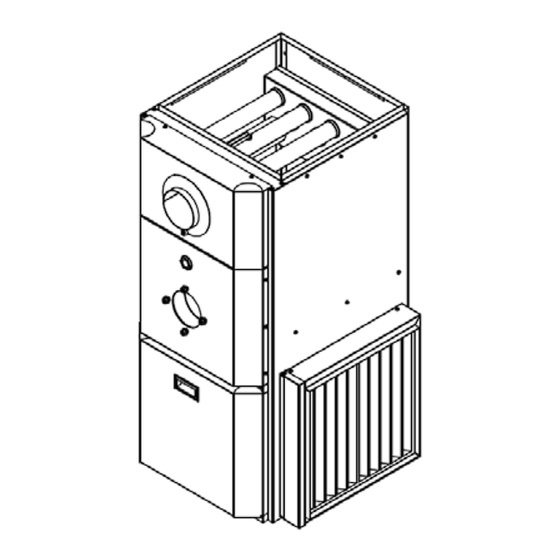
KHM-100 GAS
KHM-200 GAS
INSTALLATIONS MUST MEET ALL LOCAL AND FEDERAL
CODES THAT MAY DIFFER FROM THIS MANUAL
Please read the manual in its entirety before beginning installation.
This manual must be kept with the furnace for future reference.
GRANBY FURNACES INC.
PO Box 637
12118 Hwy 209
Parrsboro Nova Scotia Canada
B0M 1S0
902-254-2543
www.granbyindustries.com
Service Manual
SERIES
04-07-2015
KHM-100 Illustration
G2014-E2G-Rev.B
Advertisement
Table of Contents

Related Manuals for Granby KHM-100 GAS


Summary of Contents for Granby KHM-100 GAS
- Page 1 Installation, Operation and Service Manual SERIES 80% + EFFICIENCY GAS FIRED CATEGORY I HI-BOY FURNACE KHM-100 GAS KHM-200 GAS KHM-100 Illustration INSTALLATIONS MUST MEET ALL LOCAL AND FEDERAL CODES THAT MAY DIFFER FROM THIS MANUAL Please read the manual in its entirety before beginning installation.
-
Page 2: Table Of Contents
TABLE OF CONTENTS IMPORTANT SAFETY ADVICE PRODUCT INFORMATION FURNACE INSTALLATION ACCESSORY INSTALLATION BURNER INSTALLATION AND SPECIFICATIONS 5.1 ASSEMBLY & INSTALLATION OF BURNER 5.2 GAS-FIRED FURNACE LIGHTING INSTRUCTIONS 20 5.2 TECHNICAL INFORMATION FURNACE OPERATION AND SETTINGS 6.1 BLOWER SETTING 6.2 FAN TIMER CONTROL BOARD (ST9103 A 1028) 6.3 ST9103 A 1028 CONTROL BOARD SEQUENCE 6.4 SERVICING –... - Page 3 WARNING: If the information in this manual is not followed exactly, a fire or explosion may result, causing property damage, personal injury or death. - Do not store or use gasoline or other flammable vapors or liquid in the vicinity of this or any other appliance.
-
Page 4: Important Safety Advice
1.0 IMPORTANT SAFETY ADVICE Please read and understand this manual before installing, operating or servicing the furnace. To ensure you have a clear understanding of the operating procedures of the appliance please take the time to read the IMPORTANT SAFETY ADVICE section of this manual. - Page 5 • 3. The following types of installation may require OUTDOOR combustion, chemical exposures: o - Commercial buildings o - Buildings with indoor pools o - Furnaces installed in laundry rooms o - Furnaces installed in hobby or craft rooms o - Furnaces installed near chemical storage areas o Exposure to the following substances in the combustion air supply may also require OUTDOOR AIR for combustion:...
-
Page 6: Product Information
IMPORTANT This manual contains instructional and operational information for the KHM GAS FIRED FURNACE. Read the instructions thoroughly before installing furnace or starting the burner. Consult local authorities about your local FIRE SAFETY REGULATIONS. All installations must be in accordance with local state or provincial codes. - Page 7 MOTOR/BLOWER KHM-100: 1/2 hp 4 Speed / G10-8 DD or 1/2 hp ECM / G10-8 KHM-200: 3/4 hp 4 Speed / GT12-10DD or 3/4 hp ECM / GT12-10 FAN/HIGH LIMIT CONTROL Honeywell ST9103 Fan Center & Thermo-Disk (7” stem) DIMENSIONS (KHM-100) Depth 26”...
- Page 8 KHM-100 - DIMENSIONS Dimensions are in inches KHM-200 - DIMENSIONS Dimensions are in inches...
-
Page 9: Furnace Installation
3.0 FURNACE INSTALLATION GAS PIPING Gas piping must conform to local requirements. Install according to the applicable code such as NATIONAL FUEL GAS CODE ANDSI Z223.1/NFPA 54 AND/OR NATIONAL GAS AND PROPANE INSTALLATION CODE CAN/CSA B149.1. The gas piping must be installed between the gas meter and the combination gas valve (located upstream of the Riello gas burner on the furnace. - Page 10 GAS SUPPLY PRESSURE • Maximum supply pressure: 13 inches W.C. • Minimum supply pressure: 7” inches W.C. WARNING: • Do not expose the combination gas valve to gas pressures in excess of 14” W.C. The valve has a safety mechanism that interrupt the flow of gas over 14” W.C. In any event higher pressure could damage the valve seat, resulting in potentially hazardous conditions.
- Page 11 • If the gas supply pressure can exceed 14 inches of water column at any time, you must install a lockup type gas pressure regulator in the gas supply piping, ahead of the main manual gas valve on the burner. •...
- Page 12 PLACEMENT & VENTING THE INSTALLATION OF YOUR GAS-FIRED FURNACE MUST CONFORM TO THE REQUIREMENT OF THE AUTHORITY HAVING JURISDICTION OR IN THE ABSENCE OF SUCH REQUIREMENTS, TO THE NATIONAL FUEL GAS CODE ANDSI Z223.1/NFPA 54 AND/OR NATIONAL GAS AND PROPANE INSTALLATION CODE CAN/CSA B149.1.
- Page 13 4. Place in operation the appliance being inspected. Follow the lighting instructions. Adjust thermostat operation so appliance will operate continuously. 5. Test for spillage at the draft regulator outlet / draft hood opening after 5 minutes of main burner operation. Use the flame of a match or candle, or smoke from a cigarette, cigar, or pipe.
- Page 14 Connecting non-metallic vent pipe and fittings with thermal insulation shall be prohibited. Horizontal portions of the venting system shall be supported to prevent sagging by installing support every 36 inches. The horizontal runs must be sloping upwards not less than ¼ inch per foot from the boiler to the chimney connector.
- Page 15 ELECTRICAL Wire according to the National Electrical Code (Canadian Electrical Code in Canada) or local codes. Use a separately fused #12 electrical line directly from the service panel to the furnace junction box. Install a manual shut-off switch at the door or stairway to furnace room so furnace can be shut off remotely.
-
Page 16: Accessory Installation
5) Insert the threaded tube end into the pierced hole of the flue vent pipe. 6) Install the securing nut on the safety switch tube, which protrudes into the flue vent pipe. Tighten the nut securely. Figure 1- Figure 2- BVSO wiring diagram Illustration by Granby Industries... - Page 17 Wiring Instructions (BVSO) Caution: Disconnect the electrical power when wiring the unit. Wire the blocked vent switch in accordance with The National Electrical Code and applicable local codes. Wire the safety switch (BVSO) in series with the thermostat and the fan timer relay control (Figure 2).
- Page 18 AIR FILTER RACK INSTALLATION The air filter rack is shipped uninstalled inside the furnace. This way the owner can install it in the position that he wants. There are 3 possible locations to install the air filter rack which are: bottom left side, bottom right side and under the furnace.
- Page 19 Step 5: Remove the 4 knockouts on the panel (left side, right side or base panel) where you want to install the air filter Step 6: Cut the panel between the 4 knockouts. Step 7: Using 8 screws ,install the air filter rack on the furnace. Step 8: Slide the air filter inside the air filter rack...
-
Page 20: Burner Installation And Specifications
5.0 BURNER INSTALLATION AND SPECIFICATIONS 5.1 ASSEMBLY & INSTALLATION OF BURNER CONSULT THE BURNER INSTRUCTION MANUAL THAT IS INCLUDED IN THE BURNER BOX. In case of differences between the instructions on the burner instruction manual and this manual, the furnace instruction manual (this manual) must be followed. The instructions in the gas burner instruction manuals are detailed mounting, wiring, adjusting, testing and maintenance instructions that are specific to the burner used (Riello or Carlin). -
Page 21: Gas-Fired Furnace Lighting Instructions
• To restart the furnace, open again the manual gas shut-off valve that you closed a few steps back.. • Press the red button on the ignition control. The burner should then retry its ignition and light the burner. If this sequence is not respected, consult the burner manual 5.2 GAS-FIRED FURNACE LIGHTING INSTRUCTIONS... -
Page 22: Technical Information
THERMOSTAT Connect the thermostat wires to the fan timer control board (ST9103). 5.2 TECHNICAL INFORMATION KHM Series KHM-100 KHM-200 G-120 Gas G-200 Gas Riello Burner Unit Model KHM-R1-*087-03 (N/P) KHM-R2-*131-05 (N/P) Input (BTU/h) 105,000 155,000 Output (BTU/h) 87,000 131,000 Manifold Pressure 3.7‘’... -
Page 23: Furnace Operation And Settings
6.0 FURNACE OPERATION AND SETTINGS SHUTTING FURNACE DOWN POWER OFF Turn off main power breaker or disconnect. FUEL OFF Shut off manual gas supply valve. Always keep manual gas supply valve shut off if the burner is shut down for an extended period of time. -
Page 24: Fan Timer Control Board (St9103A 1028)
6.2 FAN TIMER CONTROL BOARD (ST9103A 1028) o “FAN OFF” Dip Switches adjustment Dip Switches COMFORT ADJUSTMENTS o Outlet air consistently too warm or too cold - change the blower motor speed to give the specified air temperature rise. o Outlet air gets too warm and burner shuts down - increase air by changing the blower motor speed to give the specified temperature rise. -
Page 25: St9103A 1028 Control Board Sequence
6.3 ST9103A 1028 CONTROL BOARD SEQUENCE ST9103 Heating Sequence 1) Thermostat calls for Heat. 2) Burner starts 3) Blower starts after 45 seconds 4) Burner shuts down after call for heat is satisfied 5) Blower stops according to adjusted (FAN OFF) Dip switch selection ST9103 Cooling Sequence 1) Thermostat calls for cooling 2) Blower starts immediately... -
Page 26: Servicing - Fan Timer St9103A 1028
6.4 SERVICING - FAN TIMER ST9103A 1028 Trouble shooting the electronic board ST 9103 Before trouble shooting the board, check for the 5 amp. fuse For accurate trouble shooting, follow step by step the Trouble Shooting Chart. Step Possible Cause Check-out procedure Corrective action No Heat... - Page 27 Step Possible Cause Check-out procedure Corrective action No Heat Check for 120 Volts on the Yes - Move to next step Riello burner black wire, contact (COM) No - Back to step # 4 or check for bad application on the burner activation connection relay.
-
Page 28: Service
Step Possible Cause Check-out procedure Corrective action (No) Cooling / Heating Yes - Move to next step Check for 24 Volts between No - Check thermostat and wiring; if it's Blower G and C on electronic fan OK, then change the electronic fan High speed control control... - Page 29 REGULAR MAINTENANCE Check complete operation at least once a year. Clean flue pipes on a regular basis. Replace flue pipes if there is any sign of corrosion or other problems. Gaskets should be checked and may have to be replaced. CLEANING HEAT EXCHANGER Heat exchanger must be inspected every heating season.
- Page 30 BLOWER REMOVAL This furnace has a blower sealing system, which is designed to be tight and rattle free. Refer to the instructions and pictures below. 1) Shut off oil and power to furnace. 2) Remove the two (2) screws securing the blower door (Figure 1).
-
Page 31: Burner Cleaning Notes
BURNER CLEANING NOTES Your burner manufacturer has supplied instructions for servicing and maintenance should be performed as instructed. Riello 40 G120 Gas Burner Carlin EZGas PRO Burner Burner PERFORM COMBUSTION TEST Perform an annual combustion check on the gas burner. -
Page 32: Electrical / Wiring Diagrams
8.0 ELECTRICAL / WIRING DIAGRAMS HEATING & COOLING Connection for Carlin Burner, check the Carlin burner instruction manual... -
Page 33: Exploded Parts View
9.0 EXPLODED PARTS VIEW KHM-100 – Exploded Parts View KHM-100 – Part List... - Page 34 ITEM PART NUMBER DESCRIPTION CAB-A0-0019-00 Left Panel Assembly CAB-A0-0020-00 Right Panel Assembly CAB-A0-0018-00 Rear Panel Assembly CAB-A0-0016-00 Blower Panel Assembly CAB-A0-0021-00 Front Panel Assembly CAB-A0-0022-00 20’’ x 20’’ Filter Holder Assembly CAB-P0-0045-00 Base Panel CAB-P0-0052-00 Front Door Panel CAB-P0-0051-00 Blower Door Panel 3HN-00-PULL-00 Handle Flush Pocket Pull HEX-A0-0009-00 Heat Exchanger Assembly HEX-P0-0064-00 Pipe Baffle Hi-Boy...
-
Page 35: Khm-200
KHM-200 – Part List... - Page 36 ITEM PART NUMBER DESCRIPTION CAB-A0-0027-00 Left Panel Assembly CAB-A0-0028-00 Right Panel Assembly CAB-A0-0026-00 Rear Panel Assembly CAB-A0-0024-00 Blower Panel Assembly CAB-A0-0029-00 Front Panel Assembly CAB-A0-0030-00 20’’ x 25’’ Filter Holder Assembly CAB-P0-0061-00 Base Panel CAB-P0-0065-00 Front Door Panel CAB-P0-0051-00 Blower Door Panel 3HN-00-PULL-00 Handle Flush Pocket Pull HEX-A0-0011-00 Heat Exchanger Assembly HEX-P0-0064-00 Pipe Baffle Hi-Boy...
-
Page 37: Start-Up Test Results
10. START-UP TEST RESULTS Model: Serial Number: Date of installation: Installer (name & address): START-UP TEST RESULTS Size of unit (Btu/h): Input: __________________ Manifold pressure: _____________ Chimney____________ Combustion Results: Chimney draft: “ W.C. Ambient temperature: ° F Gross flue temperature: °... - Page 38 TEST PROCEDURES External Total Static Pressure Reading A/C Coil Total Resistance Reading Coil Pressure (Pc) - Supply Pressure (Ps) Supply Pressure (Ps) + Return Pressure (Pr) Temperature Rise Reading *** Supply Temp. (Ts) - Return Temp. (Tr) *** Probe must not be in direct sight of heat exchanger.
- Page 39 Granby Furnaces Inc. manufactures a full line of furnaces in its 70,000 square feet facility. Granby products are sold across Canada and the United States through a distribution network. Our team of engineers, designers and technicians continually research and develop products to go beyond the demanding specifications of today’s certifications.
Need help?
Do you have a question about the KHM-100 GAS and is the answer not in the manual?
Questions and answers