Granby KLR-100 Installation, Operation And Service Manual

Granby KLR-100 Installation, Operation And Service Manual

Oil fired loboy furnace

Advertisement

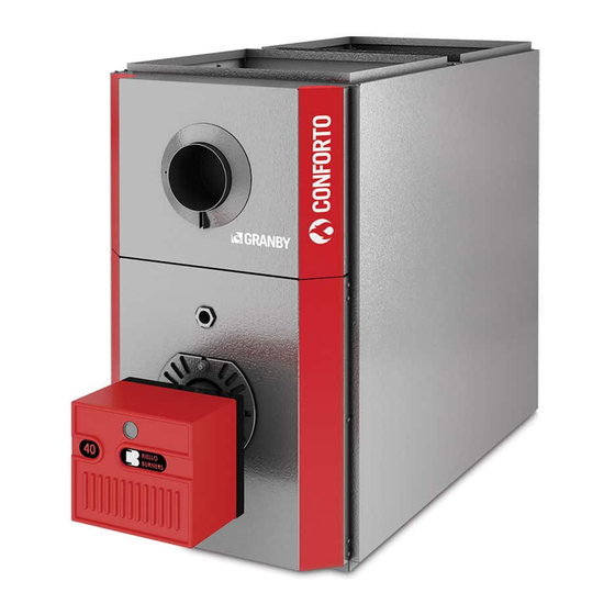
Installation, Operation and Service
OIL FIRED LOBOY FURNACE - 85% + EFFICIENCY
KLR-100
KLR-200
KLF-100
KLF-200
INSTALLATIONS MUST MEET ALL LOCAL AND
Please read the manual in its entirety before beginning installation. This
manual must be kept with the boiler for future reference. For maintenance
or question, please refer to your installer – contractor directly.
18-06-2017
Manual
KLR-100 & 200
DIFFER FROM THIS
KLF-100
KLF-200
CODES THAT MAY
G2017-E1 Rev.I

Advertisement

Table of Contents
loading
Need help?

Need help?

Do you have a question about the KLR-100 and is the answer not in the manual?

Questions and answers

Subscribe to Our Youtube Channel

Summary of Contents for Granby KLR-100

  • Page 1 Manual OIL FIRED LOBOY FURNACE - 85% + EFFICIENCY KLR-100 KLR-200 KLF-100 KLF-200 KLR-100 & 200 KLF-100 KLF-200 INSTALLATIONS MUST MEET ALL LOCAL AND CODES THAT MAY DIFFER FROM THIS Please read the manual in its entirety before beginning installation. This manual must be kept with the boiler for future reference.
  • Page 2: Table Of Contents

    SERVICING – FAN TIMER (ST9103A1028) SERVICE ELECTRICAL / WIRING DIAGRAMS HEATING & COOLING – RIELLO BURNER HEATING & COOLING – BECKETT BURNER HEATING ONLY (2 WIRES THERMOSTAT) EXPLODED PARTS VIEW KLR-100 KLR-200 KLF-100 (Coming soon, please call your Granby representative) KLF-200 START-UP TEST RESULTS...
  • Page 3: Important Safety Advice

    1.0 IMPORTANT SAFETY ADVICE Please read and understand this manual before installing, operating or servicing the furnace. To ensure you have a clear understanding of the operating procedures of the unit please take the time to read the IMPORTANT SAFETY ADVICE section of this manual. WARNINGS NEVER burn garbage or paper in the unit.
  • Page 4: Product Information

    2-1/2” (63 mm) AIR/BLOWER DATA Maximum external static pressure 0.5” WC Maximum cooling unit capacity KLR-100, up to 3.0 tons. KLR-200, up to 5.0 tons. KLF-100, up to 3.0 tons KLF-200, up to 5.0 tons. Maximum air temperature rise 85°F High Limit temperature 185°F...
  • Page 5 15” x 20” x 2” & 20” x 20” x 2” non-pleated UL approved KLF-100 20” x 20” x 2” non-pleated UL approved KLF-200 15” x 20” x 2” (2X) non-pleated UL approved PLENUM DIMENSIONS (KLR-100) Cold air return 20” x 20” (508 x 508 mm) Hot air supply 20”...
  • Page 6 21-1/2” (546 mm) DIMENSIONS (KLR-200) DIMENSIONS (KLF-200) Depth 55-1/8” (1400 mm) Depth 52-5/8” (1337 mm) Height 33” (838 mm) Height 35-1/8” (892 mm) Width 21-1/2” (546 mm) Width 21-1/2” (546 mm) KLF-100 KLF-200 KLR-100 - DIMENSIONS Dimensions are in inches...
  • Page 7 KLR-200 – DIMENSIONS Dimensions are in inches KLF-100 - DIMENSIONS Dimensions are in inches...
  • Page 8: Furnace Installation

    KLF-200 – DIMENSIONS Dimensions are in inches 3.0 FURNACE INSTALLATION OIL TANK & PIPING Tank installation must conform to local requirements. Install according to the applicable code such as CAN/CSA B139 and NFPA 31 in the USA. Minimize number of connections in suction line and make all connections air tight. Use a pipe joint compound suitable for oil on all pipe threads.
  • Page 9: Oil Tank And Piping

    REAR FLUE FURNACE ILLUSTRATION Oil Tank and Piping PLACEMENT & VENTING Furnace installation shall conform to the required installation code for oil-fired equipment (USA: NFPA 31, Canada: CAN/CSA B139). FLOOR SUPPORT COMBUSTIBLE – If required, support furnace on five (5) concrete blocks. Make sure the center of the furnace base is supported.
  • Page 10 The temperature at the base of the chimney can be increased by insulating the flue-pipe between the furnace and the chimney base. If this is not sufficient, consider cutting or removing some flue baffles in the furnace. BE AWARE THAT REMOVING BAFFLES REDUCES THE UNIT’S EFFICIENCY AND A ®...
  • Page 11 Appliance(s) located in a large space Combustion air and additional ventilation from outdoor 12’’ higher than ground level and snow forecast. The opening shall have a total free-flow area of not less than 4,4 cm /kW (1 po /5000 BTU/h) of the total input rating for the appliance(s) located in a large space.
  • Page 12: Accessories Installation

    Appliance(s) located in a limited space Combustion air from outdoors by infiltration and ventilation from inside the building 12’’ higher than ground level and snow forecast. The opening shall have a total free-flow area of not less than 4,4 cm /kW (1 po /5000 BTU/h) of the total input rating for the appliance(s) located in a limited space.
  • Page 13 Insert the threaded tube end into the pierced hole of the flue vent pipe. Install the securing nut on the safety switch tube, which protrudes into the flue vent pipe. Tighten the nut securely (Figure 1). Figure 1 - Illustration Granby Industries Figure 2 - BVSO wiring diagram Wiring Instructions (BVSO) Caution: Disconnect the electrical power when wiring the unit.
  • Page 14 AIR CONDITIONING An air conditioning coil may be installed on the supply side only. Coils installed on the return side will cause condensation on the heat exchanger; this will shorten the heat exchanger life and may cause products of combustion to enter the house. Wire as per wiring label and diagram.
  • Page 15: Burner Installation And Specifications

    5.0 BURNER INSTALLATION AND SPECIFICATIONS ASSEMBLY & INSTALLATION OF BURNER ASSEMBLY Check that the burner model is correct for furnace rating required. Assemble as per burner manufacturer’s instructions. SELECT NOZZLE Select oil input, nozzle and burner configuration as shown on furnace operating decal.
  • Page 16: Set Burner For Efficient Operation

    SET BURNER FOR EFFICIENT OPERATION BURNER SETTING Use burner settings in the table on page 18 (KLR) and 19 (KLF) or operating decal as a guide to set burner, particularly for nozzle changes. Those settings are only starting points for the adjustments and are not meant as final settings.
  • Page 17 COMBUSTION TEST All your tests must be done with the burner cover on ADJUSTMENTS After 10 minutes of normal operation, adjust the breech draft with the barometric control to obtain a value of -0.01’’ WC, after proceed to take a smoke test and adjust the burner to obtain a reading of “1” on the smoke scale.
  • Page 18: Klr Technical Information

    KLR TECHNICAL INFORMATION / BURNER AND BLOWER KLR-100 KLR-200 KLR Series Riello Burner KLR-E1-*067-03 KLR-E1-*079-03 KLR-E1-*091-03 KLR-E3-*109-05 KLR-E3-*127-05 KLR-E3-*139-05 Unit Model 0.55 0.65 0.75 0.90 1.05 1.15 Firing Rate (USGPH) 77,000 91,000 105,000 126,000 147,000 161,000 Input (BTU/H) 67,000 79,000...
  • Page 19: Klf Technical Information

    KLF TECHNICAL INFORMATION / BLOWER AND BURNER KLF Series KLF-100 KLF-200 Riello Burner KLF-E1-*067-03 KLF-E1-*079-03 KLF-E1-*091-03 KLF-E3-*102-05 KLF-E3-*119-05 KLF-E3-*132-05 Unit Model 0.55 0.65 0.75 0.85 1.00 1.10 Firing Rate (USGPH) 77,000 91,000 105,000 119,000 140,000 154,000 Input (BTU/H) 67,000 79,000 91,000 102,000 119,000...
  • Page 20: Furnace Operation And Settings

    6.0 FURNACE OPERATION AND SETTINGS SHUTTING FURNACE DOWN POWER OFF Turn off main power breaker or disconnect. FUEL OFF Shut off manual fuel supply valve. Always keep manual fuel supply valve shut off if the burner is shut down for an extended period.
  • Page 21: Comfort Adjustments

    COMFORT ADJUSTMENTS o Outlet air consistently too warm or too cold - change the blower motor speed to give the specified air temperature rise. o Outlet air gets too warm and burner shuts down - increase air by changing the blower motor speed to give the specified temperature rise.
  • Page 22 Position of the ST9103A1028 Electronic Board KLR-100 and 200 KLF-200 KLF-100...
  • Page 23: Servicing - Fan Timer St9103A1028

    SERVICING - FAN TIMER ST9103A1028 Honeywell electronic board ST9103 Before trouble shooting the board, check for the 5 amp. fuse For accurate trouble shooting, follow step by step the Trouble Shooting Chart Step Possible Cause Check-out procedure Corrective action No Heat Check for 120 Volts Yes - Move to next step between terminal S2 and...
  • Page 24 Step Possible Cause Check-out procedure Corrective action No Heat Riello burner Yes - Move to next step Check for 120 Volts on No - Back to step # 4 or check for the black wire, contact bad connection (COM) on the burner activation relay Check if oil primary Yes - Press reset button...
  • Page 25 Step Possible Cause Check-out procedure Corrective action Blower Check for 120 Volts at the Yes - Move to next step . Low speed ''CONT'' terminal on No - Change the electronic fan control the electronic fan control Yes - Check ''LOW'' speed on Check if the Check for 120 Volts on the blower motor...
  • Page 26: Service

    7.0 SERVICE / MAINTENANCE REGULAR MAINTENANCE Check complete operation at least once a year. In Canada see CAN/B139, (Maintenance), in United States refer to NFPA 31, for recommended servicing procedure. Clean flue pipes on a regular basis. Replace flue pipes if there is any sign of corrosion or other problems. Gaskets should be checked and may have to be replace.
  • Page 27: Changing Nozzle

    CHANGING NOZZLE It is recommended that the nozzle be replaced once a year. If a new nozzle of a different size is installed, change the blower speed according to section BURNER INSTALLATION AND SPECIFICATIONS or operating decal as required. AIR FILTERS To maintain furnace performance and safety, replace dirty filters at least once every heating season or as required.
  • Page 28: Electrical Wiring Diagrams

    8.0 ELECTRICAL WIRING DIAGRAMS HEATING & COOLING KLR ⁄ KLF RIELLO...
  • Page 29 HEATING & COOLING For more informations, see next page...
  • Page 30 GeniSys control schematic with the ST9103 Board...
  • Page 31 HEATING ONLY RIELLO / BECKETT...
  • Page 32: Exploded Parts View

    9.0 EXPLODED PARTS VIEW KLR-100 EXPLODED PARTS VIEW View Detoit View DetailC Detail C Fan-A0-0002-01 ECM Motor...
  • Page 33 4RY-00-24V0-00 Relay AE04001 24VAC Form C SPDT 24V HEX-A0-0012-00 Rear Collector Assembly FAN-A0-0002-00 Fan Motor Assembly KLR-100 PSC Motor FAN-A0-0002-01 Fan Motor Assembly KLR-100 ECM Motor 3BU-10-08DD-00 Blower 10'' x 8'' Direct Drive (G10-8DD) 3BM-50-4SDD-01 Motor Blower 1/2 HP Direct Drive 4SP EMERSON 4CA-00-705M-00 Capacitor 7.5 µF 370VAC 70C 60 Hz...
  • Page 34: Klr-200

    KLR-200 EXPLODED PARTS VIEW Detail A ELB-A0-0008-00 Electric box...
  • Page 35 KLR-200 – Part List ITEM PART NUMBER DESCRIPTION CAB-A0-0007- Front Panel Assembly CAB-A0-0012- Base Panel Assembly CAB-A0-0009- Right Panel Assembly CAB-A0-0008- Left Panel Assembly CAB-A0-0010- Divider Panel Assembly CAB-P0-0080- Top Rear Panel CAB-P0-0013- Blower Door Panel CAB-P0-0014- Upper Divider CAB-P0-0015- Divider's Filler Gasket Bracket 3HN-00-PULL- Handle Flush Pocket Pull...
  • Page 36: Klf-200

    KLF-200- Exploded Parts View Detail B Detail C Detail D Detail E FAN-A0-0001-00 FAN-A0-0001-01 FAN-A0-0006-00 FAN-A0-0006-01 Motor PSC 3⁄4 HP Motor ECM 3⁄4 HP Motor PSC 1⁄2 HP Motor ECM 1⁄2 HP...
  • Page 37 KLF-200 – Part List ITEM PART NUMBER DESCRIPTION CAB-A0-0049- Front Panel Assembly CAB-A0-0052- Base Panel Assembly CAB-A0-0051- Right Panel Assembly CAB-A0-0050- Left Panel Assembly CAB-A0-0053- Divider Panel Assembly CAB-P0-0164- Top Rear Panel 3HN-00-PULL- Handle Flush Pocket Pull CAB-P0-0013- Blower Door Panel ELB-A0-0018- Electrical Box Assembly CAB-P0-0128-...
  • Page 38: Start-Up Test Results

    10. START-UP TEST RESULTS Model: Serial Number: Lowboy KLR_ Lowboy KLF Date of installation: Installer (name & address): START-UP TEST RESULTS Size of unit (Btu/h): Nozzle: Oil Pressure (psi): Chimney Direct vent system (DVS) Burner adjustments: RIELLO F3 ⁄ BF3____RIELLO F5 ⁄ BF5____ BECKETT AFG-LII ____ Beckett F3 ____ Turbulator: Air Gate:...
  • Page 39 TEST PROCEDURES External Total Static Pressure Reading Total Static Pressure = Supply Pressure (Ps) + Return Pressure (Pr) A/C Coil Total Resistance Reading A/C coil total resistance = Coil Pressure (Pc) - Supply Pressure (Ps) Temperature Rise Reading *** Temperature rise = Supply Temp. (Ts) - Return Temp. (Tr) *** Probe must not be in direct sight of heat exchanger.
  • Page 40 Granby Furnaces Inc. manufactures a full line of oil-fired furnaces in its 70,000 square feet facility. Granby products are sold across Canada and the United States through a distribution network. Our team of engineers, designers and technicians continually research and develop products to go beyond the demanding specifications of today’s certifications.

This manual is also suitable for:

Klr-200Klf-100Klf-200

Table of Contents

Save PDF