
Related Manuals for Daikin E8.5064


Summary of Contents for Daikin E8.5064
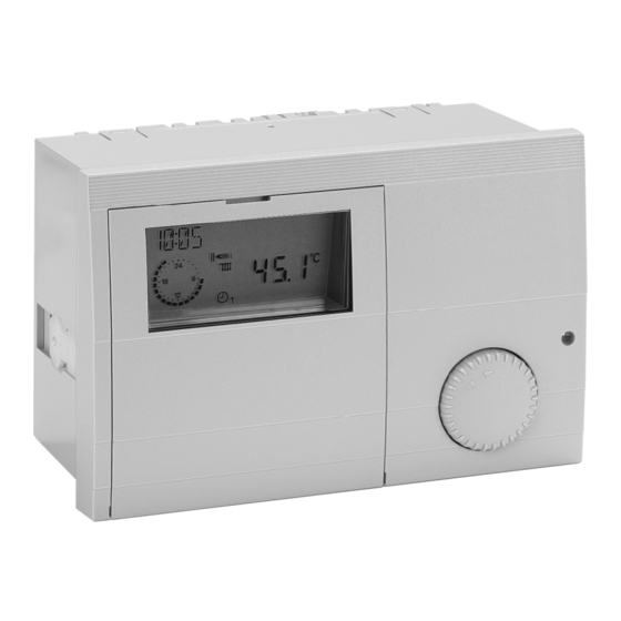
- Page 1 E8.5064 V1 System Manager Installation Manual Please observe the safety instructions and read through this manual carefully before commissioning the equipment.
-
Page 2: General Information
Safety information General information General information Safety information Warranty conditions Power connection regulations If the system is not installed, commissioned, serviced and Please note the connection conditions specified by your repaired properly, it will render the manufacturer's warranty local electrical power supply company and the VDE regula- null and void. -
Page 3: General Notes
Automatic toggle between summer and winter time Activation of a timer is possible Description Declaration of conformity We the manufacturer declare the product E8.5064 is in conformity with the fundamental requirements of the follow- ing directives and standards. Directives: – 2004/108/EC, 2006/95/EC Standards: –... -
Page 4: Table Of Contents
Inhaltsverzeichnis General information Sensors Inhaltsverzeichnis Outside sensor AF (AFS) S General information Immersion sensor KF (KFS) H/SPF (SPFS) F Safety information Strap-on sensor VF (VFAS) v Safety System bus General Notes The heating system ... - Page 5 Inhaltsverzeichnis General information Installation level Installation 03 = E8.3611 => 0 - 10 V Controller Terminal assignment Commissioning procedure Installation (selecting basic controller functions) Installation 04 = E8.0634 BUS-ID HS (- - - -) => Standard controller with 2-stage HS ...
-
Page 6: Installation
Assembly/Dismantling Installation Installation Installing the controller: Installation 1. Set the mounting clamp to the wall thickness of the con- Assembly/Dismantling trol panel (at the left and right-hand side of the unit): a. Pull the mounting clamp at the low away from the con- troller wall (toothing). -
Page 7: Electrical Connection
Electrical Connection Installation Removing the controller: After connecting or modifying the connections of sensors and remote controls the controller must be E Disconnect the unit from the power supply before briefly switched off (mains switch/fuse). The function removing it. of the controller is reconfigured in accordance with d) Insert a sharp-pointed tool at an angle with respect to the connected sensors the next time the controller is the exterior wall into one of the unlocking holes (the... -
Page 8: Connection Diagram
Electrical Connection Installation ~ 230 V; Relay switching capacity 2 (2) A, ~ 250 V Connection diagram... -
Page 9: Terminal Assignment
Electrical Connection Installation Terminal assignment Mains Sensors (1): Neutral conductor, mains VII (1+2): eBUS (FA) or 0 - 10 V output (2): Power supply, unit (1,2,3+ ): F1/F2/F3 = buffer storage tank (3): Power supply, relay low/middle/top (4): A1 = Pump heating circuit 1 (2+3+ ): FBR2 (FBR1) for heating circuit 1 (5): A1 = Pump heating circuit 2... -
Page 10: Power Terminal Assignments
Electrical Connection Installation Power terminal assignments Plug 2 [II] N: Neutral conductor, mains Options L1: Power supply, unit Provided no separate reg- L1´: Power supply to relay ulations for protecting the 1: heating circuit pump HC 1 relay apply, a bridge to 2: heating circuit pump HC 2 supply the relay must be F: Storage tank charging pump... -
Page 11: Sensor Terminal Assignments
Electrical Connection Installation Sensor terminal assignments Connector 7 [VII] Pin 1: eBUS (FA) or 0 - 10 V output Pin 2: (Ground BUS/0 - 10 V) Connector 1 [I] Pin 1: Buffer storage tank low sensor Pin 2: Buf. stor. tank middle sensor/FBR heat. circ. 1 (room sensor) Pin 3: Buf. - Page 12 Electrical Connection Installation Connector 3 [III] Pin 1: FBR heating circuit 2 (room sensor)/0 - 10 V IN/Light Pin 2: FBR heating circuit 2 (ground) Pin 3: FBR heating circuit 2 (set value)/Pulse counter for output measurement Connector 9 [IX] CAN Bus Pin 1 = H (Data) CAN Bus Pin 2 = L (Data) CAN Bus Pin 3 = - (ground, Gnd)
-
Page 13: Remote Controls
Remote controls Installation Remote controls Remote control FBR2 Electrical connection: HC1: Connector I; 2, Ground and 3 Operation-control module Merlin BM, BM 8, Lago FB HC2: Connector III; 1 - 3 (Only for controller models with CAN-Bus connection) Rotating switch for modifying room temperature setting Electrical connection: Connector IX;... -
Page 14: Sensor Resistances Fbr
Remote controls Installation Installation location: DCF receiver Electrical connection: Connector VII; Terminal 1, 2 In reference/main living room of the heating circuit The controller can evaluate a eBUS DCF receiver on the (on an inside wall of the room). eBUS FA-Terminals. -
Page 15: Maximum Delimiter
Remote controls Installation Maximum delimiter Telephone switch If a maximum delimiter is required it must be connected between the heating circuit pump and the pump controller switch output. Connector I, terminals 4 and 5 The heating system can be switched to Heating mode with a telephone switch. -
Page 16: Sensor Values/Characteristic Curve
Remote controls Installation Sensor values/characteristic curve 5 kOhm NTC: AF, KF, SPF, VF 1 kOhm PTC: AFS, KFS, SPFS, VFAS Temperature 5 kOhm NTC 1 kOhm PTC PT1000 -60 °C 698961 -50 °C 333908 The controller can be operated with 5 kOhm NTC (stand- ... -
Page 17: Sensors
Sensors Installation Strap-on sensor VF (VFAS) v Sensors Order no. VF, 5 kΩ, 3 m, ø 6.0x50: 99 679 073 Outside sensor AF (AFS) S Order no. VFAS, 1 kΩ, 3 m, ø 6.0x50: 99 679 051 Order no. AF, 5 kΩ: 99 679 030 Scope of supply Order no. -
Page 18: System Bus
System bus Input of the basic setting Input of the basic setting System bus Input of the basic setting The heating system Please ensure that you set the desired operating mode after installation is complete. 1 - 8 Boiler (modulating or switching) 1 - 15 Mixed weather-dependent heating circuits Please enter the settings in the order specified 0 - 15 Room controller (digital or analogue) -
Page 19: Ç Operating Mode Selection
Operation in normal mode Input of the basic setting Ç Operating mode selection Service (automatic reset after 15 min) Turn the knob to select the operating mode required. The Boiler regulates to boiler target temperature = maximum operating mode selected is indicated by a symbol at the boiler temperature. -
Page 20: Display In Normal Operation
Operation in normal mode Input of the basic setting Explanations Display in normal operation Current time Freely selectable display (refer to "DISPLAY SEL" parameter) DCF reception OK (only if receiver is connected) via eBUS) Bus icon (if this icon does not appear, check data line to connected CAN controllers =>... -
Page 21: Changing Set Values
Changing set values Input of the basic setting Changing set values Operating elements Ç A => Shaft encoder The operating flap must be opened first in order to change Search for value/level or adjust value or request set values. Ä =>... -
Page 22: Operating Level
Changing set values Input of the basic setting Operating level Operation is divided into different areas: General - Display - User - Time programs - Expert - General SERVICE Expert FA. DATE/TIME/HOLIDAY Opening the hinged control panel cover automatically Open Ç... -
Page 23: Areas
Changing set values Input of the basic setting Areas Levels General The settings in the different areas are sorted into operating levels Value selection summary INSTALLATION Service => for service engineers Hot water Date/Time/Holiday => for users Heating circuit I Display ... -
Page 24: Installation Level
Installation level Input of the basic setting Installation level Installation level Designation Value range Default Installation level INSTALLATION ----, 01 - 06 ---- All the values in this level must be entered in sequence without interruption BUS-ID HS ----, 01 - 08 ---- Ä... -
Page 25: Hs 1 Type (Primary Heat Generator Type)
Installation level Input of the basic setting BUS-ID HS (- - - -) HS 2 TYPE (secondary heat generator type HS => A7) (not an option in all models) (For HS1 with 2-stage burner – not active) The controller will be used as cascade with setting 00 = No secondary heat generator "01 - . -
Page 26: Buffer (Heater Buffer Storage Type)
Installation level Input of the basic setting 00 = no buffer storage for heating operation Switching pattern 01 = Buffer storage for heating operation (F1 - F3) Switching the pump on is done if the temperature of the (Sensor switching- in V1 no other function) solid fuel boiler exceeds the temperature of the Reference 02 = Combination storage tank for heating and HW opera- sensor by the hysteresis (HYST BURNER2 + 5 K). -
Page 27: Cap/Stage (Boiler Output For Each Stage)
Installation level Input of the basic setting [T-POOL 1/2/3]. The heating program operates. CAP/STAGE (boiler output for each stage) No heating takes place during the reduction period (frost Display of the HS number and the stage => Selection with protection only). Prog button =>... -
Page 28: Auxiliary Relay Functions
Installation level Input of the basic setting RELAY FUNC 1 (function selection relay MF1) Solar/MF T-MF1 SETP (switching temperature relay MF1) Designation Value range Default MF 1 HYST (hysteresis relay MF1) RELAY FUNC (1-4) 00 - 26 00,00,01,02 T-MF(1-4) SETP 30 °C - 90 °C 30 °C 00 = No MF function... - Page 29 Installation level Input of the basic setting 22 = Solid fuel boiler integration 06 = Pump HS2 (e.g. in connection with 2-stage HS) When using the controller to control two heat generators the relay T-MF1 or 1 - 4 = Temperature of the solid fuel boiler may be used to control the pump for HS 2.
- Page 30 Installation level Input of the basic setting 23 = Solar integration (to MF4 because of PT1000 sen- The return flow temperature increase pump is switched on sor) if the return flow temperature drops below the temperature setting limit (T-MF1 SETP). It is switched off again when T-SOL PANEL [T-MF4] = Temperature of the solar collec- the return flow temperature exceeds the temperature set- ting limit by the Hysteresis (MF 1 HYST).
-
Page 31: F15 Function (Sensor Function F15)
Installation level Input of the basic setting F15 FUNCTION (sensor function F15) Heating circuit/Sensors 00 = Room sensor for heating circuit 2. If a further sensor Designation Value range Default at the pulse input [IMP] is detected at this position an FBR BUS ID 1 00 - 15 is evaluated. -
Page 32: Choice Of Installation
Schematic circuit diagrams hydraulic system Choic Choice of installation Alternatively: Isolating circuit for Schematic circuit diagrams hydraulic system hot water preparation Installation 01 = E8.4034 => Cascade controller for modulating HS... -
Page 33: Terminal Assignment
Schematic circuit diagrams hydraulic system Choice of installation Terminal assignment Mains Sensors (1): Neutral conductor, mains VII (1+2): eBUS (to heat generators/FA) (2): Power supply, unit (2+3+ ): optional FBR2 (FBR1) for heating circuit 1 (3): Power supply, relay (2+ ): optional F2 = Room sensor for heating (4): A1 = Pump heating circuit 1... -
Page 34: Installation 02 = E8.4834
Schematic circuit diagrams hydraulic system Choic Alternatively: Isolating circuit for Installation 02 = E8.4834 => hot water preparation Cascade controller for switching HS... -
Page 35: Terminal Assignment
Schematic circuit diagrams hydraulic system Choice of installation Terminal assignment Mains Sensors (1): Neutral conductor, mains (2+3+ ): optional FBR2 (FBR1) for heating circuit 1 (2): Power supply, unit (2+ ): optional F2 = Room sensor for heating (3): Power supply, relay circuit 1 (4): A1 = Pump heating circuit 1... -
Page 36: Installation 03 = E8.3611 => 0 - 10 V Controller
Schematic circuit diagrams hydraulic system Choic Installation 03 = E8.3611 => 0 - 10 V Controller... -
Page 37: Terminal Assignment
Schematic circuit diagrams hydraulic system Choice of installation Terminal assignment Mains Sensors (1): Neutral conductor, mains (2+3+ ): optional FBR2 (FBR1) for heating circuit 1 (2): Power supply, unit (2+ ): optional F2 = Room sensor for heating (3): Power supply, relay circuit 1 (4): A1 = Pump heating circuit 1... -
Page 38: Installation 04 = E8.0634 => Standard Controller With 2-Stage Hs
Schematic circuit diagrams hydraulic system Choic Installation 04 = E8.0634 => Standard controller with 2-stage HS... -
Page 39: Terminal Assignment
Schematic circuit diagrams hydraulic system Choice of installation Terminal assignment Mains Sensors (1): Neutral conductor, mains (2+3+ ): optional FBR2 (FBR1) for heating circuit 1 (2): Power supply, unit (2+ ): optional F2 = Room sensor for heating (3): Power supply, relay circuit 1 (4): A1 = Pump heating circuit 1... -
Page 40: Installation 05 = 2Hs Controller => 2 Hs Cascade Switched Via Relay
Schematic circuit diagrams hydraulic system Choic Installation 05 = 2HS controller => 2 HS cascade switched via relay... -
Page 41: Terminal Assignment
Schematic circuit diagrams hydraulic system Choice of installation Terminal assignment Mains Sensors (1): Neutral conductor, mains (2+3+ ): optional FBR2 (FBR1) for heating circuit 1 (2): Power supply, unit (2+ ): optional F2 = Room sensor for heating (3): Power supply, relay circuit 1 (4): A1 = Pump heating circuit 1... -
Page 42: Service
Error Messages Service If a fault or error occurs in the heating system, you will see Service Error Messages a blinking warning triangle (E) and the related error num- Error Error description Sensor defective (break/short circuit) Communication error E 78 F8: Boiler sensor/Collector sensor (cascade) E 90 Adr. -
Page 43: Troubleshooting
Troubleshooting Service In mixer motor expansion controllers with connection to Troubleshooting Boiler controller => Outside temperature and boiler tem- perature display (see "Display/Installation") General Control unit => Room temperature displayed and current If your system malfunctions you should first check that the room temperature setting blanked out "----"... - Page 44 Troubleshooting Service Burner does not switch of at correct time Check minimum boiler temperature and type of minimum delimiter => Protect from corrosion Burner will not switch on Check boiler temperature setting => The temperature set- ting must be greater than the boiler temperature. (test B) Check operating mode =>...
-
Page 45: Dimensions
Dimensions Dimensions... -
Page 46: Technical Data
Technical Data Technical Data AC 230 V 10 % Supply voltage to EN 60038 Power consumption Max. 8 W Switching capacity of the relays AC 250 V 2 (2) A Maximum current on terminal L1' 10 A Enclosure to EN 60529 IP40 Safety class II to EN 60730-1 Totally insulated... -
Page 47: Glossary
Glossary Glossary Mixed heating circuit/Mixer circuit In the mixed heating circuit a three-way valve is used to Flow and return flow temperature add cooled water from the return flow to the hot flow water. The flow temperature is the temperature to which the heat The flow temperature is thus reduced. - Page 48 Glossary If you have any technical questions, please contact your local branch office/agent. The addresses are available on the Internet or from Elster GmbH. We reserve the right to make technical modifications in the interests of progress. Elster GmbH Geschäftssegment Comfort Controls Kuhlmannstraße 10 31785 Hameln...
Need help?
Do you have a question about the E8.5064 and is the answer not in the manual?
Questions and answers