Sign In
Upload
Manuals
Brands
Daikin Manuals
Control Unit
E8.5064
Daikin E8.5064 Manuals
Manuals and User Guides for Daikin E8.5064. We have
1
Daikin E8.5064 manual available for free PDF download: Installation Manual
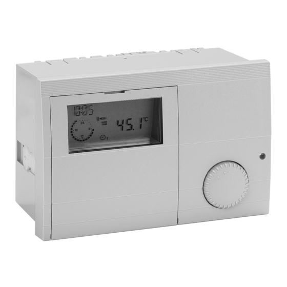
Daikin E8.5064 Installation Manual (48 pages)
V1; System Manager
Brand:
Daikin
| Category:
Control Unit
| Size: 3.57 MB
Table of Contents
General Information
2
Safety Information
2
Safety
2
General Notes
3
Description
3
Declaration of Conformity
3
Function
3
Table of Contents
4
Inhaltsverzeichnis
4
Installation
6
Assembly/Dismantling
6
Electrical Connection
7
Connecting Instructions
7
Connection Diagram
8
Terminal Assignment
9
Power Terminal Assignments
10
Sensor Terminal Assignments
11
Remote Controls
13
Operation-Control Module Merlin BM, BM 8, Lago FB
13
Remote Control FBR2
13
Sensor Resistances FBR
14
DCF Receiver
14
Maximum Delimiter
15
Telephone Switch
15
Sensor Values/Characteristic Curve
16
Sensors
17
Outside Sensor AF (AFS) S
17
Immersion Sensor KF (KFS) H/SPF (SPFS) F
17
Strap-On Sensor VF (VFAS) V
17
System Bus
18
The Heating System
18
Bus ID
18
Input of the Basic Setting
18
Operation in Normal Mode
18
Operating Elements
18
Ç Operating Mode Selection
19
Effect of the Operating Mode
19
Display in Normal Operation
20
Changing Set Values
21
Operating Elements
21
Operating Level
22
Areas
23
General
23
Display
23
User
23
Time Programs
23
Expert
23
Expert FA (Only for FA Via BUS)
23
Levels
23
Installation
23
Hot Water
23
Installation Level
24
Commissioning Procedure
24
Installation (Selecting Basic Controller Functions)
24
Bus-ID Hs
24
HS 1 TYPE (Primary Heat Generator Type)
25
HS1 BUS (Connection for HS)
25
Hs 2 Type
25
(Secondary Heat Generator Type HS => A7)
25
STORAGE HS2 (Heat Accumulator for HS2)
25
BUFFER (Heater Buffer Storage Type)
26
Hc Function
26
(Heating Circuit Function Selection)
26
CAP/STAGE (Boiler Output for each Stage)
27
Auxiliary Relay Functions
28
RELAY FUNC 1 (Function Selection Relay MF1)
28
T-Mf1 Setp
28
(Switching Temperature Relay MF1)
28
MF 1 HYST (Hysteresis Relay MF1)
28
F15 FUNCTION (Sensor Function F15)
31
BUS ID (Heating Circuit Number)
31
5 K Sensors/1 K Sensors
31
Choice of Installation
32
Schematic Circuit Diagrams Hydraulic System
32
Installation 01 = E8.4034 => Cascade Controller for Modulating HS
32
Terminal Assignment
33
Installation 02 = E8.4834
34
Cascade Controller for Switching HS
34
Terminal Assignment
35
Installation 03 = E8.3611 => 0 - 10 V Controller
36
Terminal Assignment
37
Installation 04 = E8.0634 => Standard Controller with 2-Stage HS
38
Terminal Assignment
39
Installation 05 = 2HS Controller => 2 HS Cascade Switched Via Relay
40
Terminal Assignment
41
Service
42
Error Messages
42
Troubleshooting
43
Dimensions
45
Technical Data
46
Glossary
47
Advertisement
Advertisement
Related Products
Daikin EK2MV2B10C5
Daikin EK2MV3B10C5
Daikin EK4MV2B10C5
Daikin EK4MV3B10C5
Daikin EHS157056
Daikin E2MV03B6
Daikin E2MV06B6
Daikin E2MV2V207A6
Daikin E2MV2B07A6
Daikin E4MV06B6
Daikin Categories
Air Conditioner
Heat Pump
Remote Control
Chiller
Fan
More Daikin Manuals
Login
Sign In
OR
Sign in with Facebook
Sign in with Google
Upload manual
Upload from disk
Upload from URL