McCulloch ROB R600 Operator's Manual
Hide thumbs
Also See for ROB R600:
- Manual (56 pages) ,
- Operator's manual (52 pages) ,
- Quick manual (8 pages)

Related Manuals for McCulloch ROB R600


Summary of Contents for McCulloch ROB R600
- Page 1 Operator's manual ROB R600, ROB R800, ROB R1000 EN, English Read the operator's manual carefully and make sure that you understand the instructions before you use the product.
-
Page 2: Table Of Contents
3.12 Menu structure........... 21 3.13 Timer..............22 3.14 Installation - ROB R800, ROB R1000....24 3.15 Security.............. 25 3.16 Settings.............. 26 3.17 Menu structure overview, ROB R600....28 3.18 Menu structure overview, ROB R800, ROB R1000.................29 3.19 Yard layout examples.........30 4 Operation 4.1 Main switch............ -
Page 3: Introduction
The Product registration key is a valuable document and must be stored in a safe place. This key is necessary for example to register the produkt on McCULLOCH's website or unlock the robotic lawnmower in the event of a lost PIN code. - Page 4 1.2.4 Movement pattern The movement pattern of the robotic lawnmower is random, which means that a movement pattern is never repeated. With this cutting system the lawn is mown evenly without any mowing lines from the robotic lawnmower. The blades must be in good condition to obtain the best mowing result.
-
Page 5: Product Overview
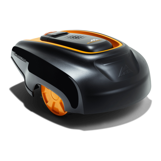
1.3 Product overview The numbers in the illustration represent: 15. Display 16. Loop wire for boundary loop and guide wire 1. Body 17. Low voltage cable 2. Cover to display, keypad and cutting height 18. Connector for connecting the loop wire to the adjustment charging station 3. -
Page 6: Symbols On The Product
1.4 Symbols on the product The low voltage cable must not be shortened, extended or spliced. These symbols can be found on the robotic lawnmower. Study them carefully. Do not use a trimmer nearby the low voltage cable. Be careful when trimming WARNING: Read the user in- edges where the cables are placed. -
Page 7: Safety
2 Safety 2.1 Safety definitions 2.2 General safety instructions Warnings, cautions and notes are used to point out The following system is used in the Operator’s Manual specially important parts of the operator's manual. to make it easier to use: italics is a text that is shown on the •... - Page 8 Please read the Operator’s Manual • McCULLOCH does not guarantee full compatibility carefully and make sure you understand the between the robotic lawnmower and other types of instructions before using the robotic lawnmower.
- Page 9 2.3.4 In the event of a thunderstorm 3. Carry the robotic lawnmower by the handle under the robotic lawnmower with the blade disc away from the body. To reduce the risk of damage to electrical components in the robotic lawnmower and its charging station, we recommend that all connections to the charging station are disconnected (power supply, boundary wire and guide wires) if there is a risk of a thunderstorm.
-
Page 10: Installation
20 m / 65 ft. length are available as optional accessories. No parts of the power supply must be McCULLOCH ROB R600 / ROB R800 / ROB R1000 changed or tampered with. For example the low voltage cable must not be shortened or extended. -
Page 11: Charging Station
3. Read carefully through all the steps before the • Protection from water spray for instance from installation. irrigation. 4. Check that all parts for the installation are included. • Protection from direct sunlight. Presentation on page 10 . • Place it in the lower part of a working area that has a major slope. - Page 12 WARNING: Applicable to USA/Canada. If power supply is installed outdoors: Risk of Electric Shock. Install only to a covered Class A GFCI receptacle (RCD) that has an enclosure that is weatherproof with the attachment plug cap inserted or removed. No parts of the power supply must be changed or If the installation is done in a working area with a steep tampered with.
-
Page 13: Charging The Battery
permitted to place the power supply on the ground. min 30 cm / 12” CAUTION: It is not permitted to make new holes in the base plate. Only the existing holes may be used to secure it to the ground. WARNING: No parts of the power supply must under any circumstances be changed or tampered with. - Page 14 have grown over the wire making it no longer visible. 3.5.2 Working area boundaries Use a hammer/plastic mallet and pegs. Depending on what the working area is adjacent to, the • Bury the wire. boundary wire must be laid at different distances from obstacles.
- Page 15 When the working area is divided by a paving stone path that is level with the lawn, it is possible to allow the robotic lawnmower to run over the path. It can be an advantage to lay the boundary wire under the paving stones.
- Page 16 15- % Secondary area >15 cm / >6" 100 cm / 40" However, the boundary wire can be laid across a slope steeper than 15% if there is an obstacle that the robotic lawnmower is allowed to collide with, for example, a Main area fence or a dense hedge.
- Page 17 • Use a hammer to knock the pegs into the ground. Exercise care when knocking the pegs and make sure the wire is not under strain. Avoid sharp bends. If the boundary wire is to be buried: • Make sure to lay the boundary wire at a minimum of 1 cm / 0.4 in.
-
Page 18: Connecting The Boundary Wire
the coupler fully. Use a polygrip to completely press 4. Press the connector onto the metal pin, Press the down the button on the coupler. connector onto the contact pin, marked L (left) and R (right), on the charging station.Carefully check that the connector is properly fitted. - Page 19 • The robotic lawnmower follows the guide wire on the same side of the wire to and from the charging station. This means that the guide wire max. is to the right of the robotic lawnmower when the distance mower travels to the charging station while it is to the left of the mower when the mower travels min.
-
Page 20: Checking The Installation
Installation of the guide performed as described in wire on page 18 . Then carry out a new calibration. Calibrate guide, ROB R600 on page 27 for ROB R600 and Test settings on page 24 for ROB R800, ROB R1000. -
Page 21: Control Panel
The keypad consists of 4 groups of buttons: the left. This means that these options are selected. OK . Check or uncheck the box by pressing 3.12 Menu structure The main menu for the ROB R600 offers 3 options: • Timer • Security •... -
Page 22: Timer
The lawn should not be cut too often to obtain the best mowing result. When the robotic lawnmower is allowed to mow too much, the lawn may appear flattened. Besides, the robotic lawnmower is subjected to unnecessary wear. If the working area is less than the robotic lawnmower's area capacity, the quality of the grass can be further improved if it is cut every other day instead of a few hours every day. - Page 23 3.13.1 Timer suggestions ROB R600 Work area Work days per week Work hours per day Suggested time interval 100 m / 1100 sq. ft 07:00 am - 10:00 am 07:00 am - 9:30 am 200 m / 2200 sq. ft...
-
Page 24: Installation - Rob R800, Rob R1000
3.14 Installation - ROB R800, ROB R1000 • The following five options can be selected; Never (0%) Rarely (approx. 20%) INSTALLATION Medium (approx. 50%) Remote start 1 Often (approx. 80%) Remote start 2 Always (100%) Test settings Select the percentage that corresponds to the size Drive past wire of the remote area relative to the total working area. -
Page 25: Security
Park the robotic lawnmower in the charging station and Test OUT - Remote start 1 . The robotic select lawnmower will then leave the charging station straight SECURITY away along the guide wire and begin mowing after the Change PIN code designated distance. -
Page 26: Settings
Place the cursor at the required country and press OK . ECO mode is suitable to use where there is other 3.16.5 Remote start, ROB R600 wireless equipment not compatible with the robotic One important function with the guide wire is the lawnmower e.g.certain hearing loops or garage doors. - Page 27 3.16.6 Calibrate guide, ROB R600 Calibrate guide function allows you to test if the robotic lawnmower can follow the guide wire out from the charging station. To test the guide wire: 1. Place the robotic lawnmower in the charging station.
-
Page 28: Menu Structure Overview, Rob R600
3.17 Menu structure overview, ROB R600 Timer Work Work Work Reset hours 1 hours 2 days timer Security Change Security level PIN code loop signal Medium High Settings Time & date Language Country Remote start Calibrate Reset user About mode... -
Page 29: Menu Structure Overview, Rob R800, Rob R1000
3.18 Menu structure overview, ROB R800, ROB R1000 Timer Work Work Work Reset hours 1 hours 2 days timer Installation Test Remote start 1 Remote start 2 Drive past settings wire Test in Test out Remote Remote Proportion Distance start 1 start 2 Always Never... -
Page 30: Yard Layout Examples
Different layouts require different settings. The following pages outline a number of layout examples with installation proposals and settings. The recommended timer settings in the following examples are applicable to ROB R600 unless otherwise stated. There is more installation help on www.mcculloch.com. Select country, then enter the supportpages for more information and videos. - Page 31 3.19.3 A number of islands and a 25% slope Area 600 m / 4300 sq. ft. Timer 7 am - 11 pm (factory setting) Monday-Sunday 270˚ Remote start - Rarely (factory setting) Proportion Remarks Place the charging station in the low- er part of the working area.
- Page 32 3.19.6 Unsymmetrical working area with a narrow passage and a number of islands Area 150 m / 1600 sq. ft. Timer 7 am - 5 pm Monday, Wednesday, Friday 2 m / 7 ft Remote start - Rarely (factory setting) Proportion Remarks The guide wire must be placed along...
-
Page 33: Operation
4 Operation 4.1 Main switch 4.3 Operation selection The operation selection button is symbolised by a WARNING: Read the safety instructions house. When the button has been pressed, the selected carefully before you start your robotic operation mode is shown in the display. By lawnmower. -
Page 34: Stop
50 / 538 The times used in this example are applicable to ROB R600, but the principle is the same for the other models. McCULLOCH ROB R1000 48 / 520 Timer setting Period 1 (A): 06:00 - 17:00 34 - Operation... -
Page 35: Charge A Flat Battery
17:00. It will begin again at 20:00 but stops running at 23:00 due to standby mode until it starts again at 06:00. When the McCULLOCH robotic lawnmower is new or has been stored for a long period, the battery will be flat and needs to be charged before starting. -
Page 36: Maintenance
For better operating reliability and longer service life: check and clean the robotic lawnmower regularly and replace worn parts if necessary. All maintenance and servicing must be done according to McCULLOCH's Guarantee terms on page 50 . instructions. See When the robotic lawnmower is first used, the blade disc and blades should be inspected once a week. -
Page 37: Battery
5.5 Winter service before winter storage. If the battery is not fully charged it can be damaged and in certain cases Take your robotic lawnmower to a local McCULLOCH be rendered useless. representative for service prior to winter storage. Regular winter service will maintain the robotic... - Page 38 • Testing the mower’s battery capacity as well as a recommendation to replace battery if necessary. • If necessary the local McCULLOCH representative can also update the robotic lawnmower with new software, including new features where applicable. 38 - Maintenance...
-
Page 39: Troubleshooting
6.2 Messages Below a number of messages are listed which may be shown in the display of the robotic lawnmower. Contact your local McCULLOCH representative if the same message appears often. Message Cause... - Page 40 Wrong PIN code has been entered. Five at- Enter the correct PIN code. Contact your lo- tempts are permitted, and the keypad is then cal McCULLOCH representative if you forget blocked for five minutes. the PIN code. Wheel motor overloa-...
- Page 41 Message Cause Action Stuck in charging sta- There is an object in the way of the robotic Remove the object. tion lawnmower preventing it from leaving the charging station. Upside down The robotic lawnmower is leaning too much Turn the robotic lawnmower the right way up. or has turned over.
-
Page 42: Indicator Lamp In The Charging Station
For a fully functional installation, the indicator lamp in the charging station must emit a solid green light. If something else appears, follow the troubleshooting guide below. If you still need help with troubleshooting, please contact your local McCULLOCH representative. Light... -
Page 43: Symptoms
If your robotic lawnmower does not work as expected, follow the troubleshooting guide below. There is a FAQ (Frequently Asked Questions) on www.mcculloch.com which provides more detailed answers to a number of standard questions. Contact your local McCULLOCH representative if you still cannot find the reason for the fault. -
Page 44: Find Breaks In The Loop Wire
Symptoms Cause Action Clean The robotic lawnmow- Grass or other foreign object blocks the blade Remove and clean the blade disc. See the robotic lawnmower on page 36 . er mows for shorter disc. periods than usual between charges. Battery on page 37 . Both the mowing and The battery is spent. - Page 45 Guide To rectify the fault you will need boundary wire, connector(s) and coupler(s): a) If the suspected boundary wire is short then it is easiest to exchange all of the boundary wire between L and the point where the guide wire is connected to the boundary wire (thick black line).
- Page 46 and connect a new boundary wire to L. Connect the other end of this new wire at the middle of the suspected wire section. Follow the same approach as in 3 a) and 3b) above. 5. When the break is found, the damaged section must be replaced with a new wire.
-
Page 47: Transportation, Storage And Disposal
You can also hang the For removal the battery from the robotic lawnmower see robotic lawnmower on a McCULLOCH original wall Battery on page 37 . hanger. Contact your local McCULLOCH representative for more information about available wall hangers. -
Page 48: Technical Data
8 Technical data 8.1 Technical data Dimensions ROB R600 ROB R800 ROB R1000 Length, cm /in. 60 / 24 60 / 24 60 / 24 Width, cm / in. 44 / 17 44 / 17 44 / 17 Height, cm / in. - Page 49 Mowing ROB R600 ROB R800 ROB R1000 Maximum length boundary wire, m / ft. 400 / 1300 400 / 1300 400 / 1300 Maximum length guide wire, m / ft. 100 / 350 100 / 350 100 / 350 Working capacity, m / acre, +/- 20% 600 /0.15...
-
Page 50: Warranty
The blades are seen as disposable and are not covered by the guarantee. If an error occurs with your McCULLOCH robotic lawnmower, please contact your local McCULLOCH representative for further instructions. Please have the receipt and the robotic lawnmower’s serial number at... - Page 51 358 - 002 - Warranty - 51...
- Page 52 Copyright © 2017 Husqvarna AB. All rights reserved. McCulloch and other product and feature names are trademarks of the Husqvarna Group. All measurements quoted are approximate. www.mcculloch.com Original instructions 1159065-95 2017-10-06...
Need help?
Do you have a question about the ROB R600 and is the answer not in the manual?
Questions and answers
How to reset or solve tilt problem
To reset the McCulloch ROB R600:
1. Select "Reset user settings" from the menu.
2. Press OK.
3. Enter the PIN code and press OK.
To solve tilt problems with the charging station:
1. Ensure the charging station is placed on flat, horizontal ground.
2. Confirm it is not tilted or bent.
This answer is automatically generated