Table of Contents
Advertisement
Quick Links
Advertisement
Table of Contents

Related Manuals for Toa AM-CF1B


Summary of Contents for Toa AM-CF1B
- Page 1 INSTRUCTION MANUAL INTegRATed AUdIO COLLAbORATION SySTeM AM-CF1b, AM-CF1W Thank you for purchasing TOA’s Integrated Audio Collaboration System. Please carefully follow the instructions in this manual to ensure long, trouble-free use of your equipment.
-
Page 2: Table Of Contents
TAbLe OF CONTeNTS 1. SAFeTy PReCAUTIONS ................3 2. geNeRAL deSCRIPTION ................5 3. FeATUReS ......................5 4. NOMeNCLATURe ANd FUNCTIONS ..........6 5. CONNeCTION eXAMPLeS ................ 8 6. INSTALLATION ....................8 7. CONNeCTIONS ....................9 7.1. AC Adapter Connection ..................9 7.2. -
Page 3: Safety Precautions
AC outlet and • Install the unit only in a location that can structurally contact your nearest TOA dealer. Make no further support the weight of the unit and the mounting attempt to operate the unit in this condition as this bracket. - Page 4 • Do not touch a power supply plug during thunder When the Unit is in Use and lightning, as this may result in electric shock. • Do not place heavy objects on the unit as this may cause it to fall or break which may result in personal injury and/or property damage. In addition, the CAUTION object itself may fall off and cause injury and/or damage.
-
Page 5: General Description
à l’établissement d’une communication satisfaisante. 2. geNeRAL deSCRIPTION The AM-CF1B and AM-CF1W Integrated Audio Collaboration Systems are designed to be used in huddle rooms or workspaces. Software web conferences can be carried out more effectively over laptops by connecting the AM-CF1 to the PCs or web cameras. -
Page 6: Nomenclature And Functions
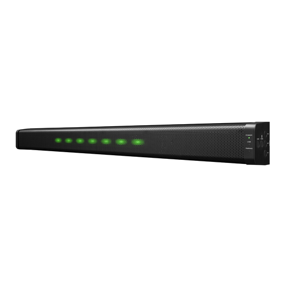
4. NOMeNCLATURe ANd FUNCTIONS [Front] [Side] 1. Power switch 4. Multifunction indicator (green/red) Hold down this switch for 3 seconds or more to This indicator is housed inside the front panel and switch between normal operation and power provide 3 different displays using 7 LEDs. Lighting standby mode. - Page 7 6. bluetooth Indicator (blue) 9. Volume Up Switch Remains lit while Bluetooth is connected. Increases the volume of the AM-CF1 unit’s internal Flashes during pairing registration. speaker when pressed. 7. Reset Switch 10. Mute Switch Used to reset the AM-CF1 unit. Mutes sound picked up at the microphone.
-
Page 8: Connection Examples
5. CONNeCTION eXAMPLeS HDMI Video 3rd party Conference controls Webcam System Polycom Control In/Out PoE Extender (DC 52V) AM – CF1 Codec In/Out AC Adapter AUX OUT (DC 12V) AUX IN Sound Mixer/ Bluetooth ® Source Amplifier Device 6. INSTALLATION Follow the procedures below to mount the AM-CF1 unit to a wall: Be sure to use the following wall mounting brackets and screws. -
Page 9: Connections
Step 3. Hook the unit’s lower mounting tab (A in the figure at right) into the mounting bracket mounted on the wall. Step 4. Make necessary connections. For connection method, see p. 9. Step 5. Bind connected wires using a tying tool or the like. Step 6. After connection is completed, tilt the unit upward with the tab hooked in Step 3 as a supporting point. -
Page 10: Pc And Usb Devices Connections
7.3. PC and USb devices Connections From USB devices From PC Notes on PC Port Connection (1) Handle connectors with care because excessive external force may damage the connectors. (2) To extract the plug, hold the plug body itself and remove it straight away from the receptacle. Do not pull on the cable to extract the plug as this may damage the connector. Correct insertion direction Do not pull on the cable. 7.4. AUX Input Connection AUX input jacks are intended exclusively for stereo input (LINE level). When connecting a monaural sound source, connect the L line. [AUX input] RCA pin jack x2 −10 dB* , 10 kΩ, unbalanced R line L line 0 dB = 1 V From sound source device... -
Page 11: Aux Output Connection
7.5. AUX Output Connection Use the supplied removable terminal plugs (6 pins) for connection. AUX output is set to LINE level input. For removable terminal plug connections, see p. 12. L line [Using a 2-core shielded wire] From mixer or From mixer or amplifier amplifier... -
Page 12: Codec Input And Output Connections
7.7. Codec Input and Output Connections From Codec output From Codec input CODEC CODEC [Codec input] [Codec output] RCA pin jack, RCA pin jack, −10 dB*, 10 kΩ, unbalanced −10 dB*, 600Ω, unbalanced * 0 dB = 1 V 7.8. Removable Terminal Plug Connection Use the removable terminal plugs supplied with the AM-CFI unit to [Cable end treatment] connect the terminals by following the instructions below. -
Page 13: System Settings
8. SySTeM SeTTINgS 8.1. Overview of System Settings Connecting the AM-CF1 unit to a PC by way of a LAN cable allows the following function settings and maintenance to be performed using the PC’s browser: [Unit Settings] • Network settings • Clock settings • User account settings [Operation Settings] • Volume adjustment and current value confirmation of various audio inputs and outputs... -
Page 14: Operation
9. OPeRATION 9.1. Turning Power ON and OFF Connecting an AC adapter or a PoE extender (p. 9) to the AM-CF1 unit turns ON the power. In about approximately 60 seconds, the unit is set to “Normal Operation” mode and can be used. After use, switch the unit to “Power Standby” mode. When using the unit again, switch back to “Normal Operation” mode. Each state of operation is shown as follows by the Power indicator: Operating Status Lighting Status Blue... -
Page 15: Bluetooth Pairing
9.4. bluetooth Pairing Step 1. Perform pairing operation on the connected peripheral device. Step 2. Hold down the Bluetooth Pairing switch for 3 seconds or more. The Bluetooth indicator flashes. Bluetooth indicator Step 3. Confirm that the unit’s name is displayed on the peripheral device screen. Step 4. Perform connection operation. Note To cut off the connection while making the Bluetooth connection, hold down the Bluetooth Paring switch for 3 seconds or more. -
Page 16: Microphone Muting
9.6. Microphone Muting Sound picked up at the microphone can be muted when in Normal Operation mode. Step 1. Press the Mute button. Sound picked up by the microphone is silenced. The Multifunction indicator continuously lights red during muting. Multifunction indicator Note: Whether all 7 LEDs or only 1 LED in the center light can be set using the web app. (See p. 13.) Step 2. -
Page 17: Contact Input Settings
10.2. Contact Input Settings The following functions can be set for each terminal: [Mute (Momentary/Latch)] Mutes sound picked up at the microphone. The mute/unmute control method differs depending on the settings. Momentary: Between Mute and Unmute when the terminal is shorted to the C terminal. Latch: Be set to Mute when the terminal is shorted to the C terminal, and to unmute when opened. -
Page 18: Initialization
11. INITIALIzATION Follow the procedure below to restore the AM-CF1 unit to its default setting values: Step 1. Press the Reset switch. The Power indicator lights blue and thereafter flashes blue-green. Power indicator Blue Blue-green Step 2. Hold down the Power switch while confirming that the Power indicator is flashing blue-green. After approximately 30 seconds, the Power indicator will light green and the USB connection indicator will light blue after flashing green. -
Page 19: Software License Information
For Specific Open-Source Software Information Please contact your nearest TOA dealer if you require details about any of the open-source software incorporated within the AM-CF1. However, we are unable to respond to inquiries about the contents of the open source. -
Page 20: Specifications
13. SPeCIFICATIONS Model Number AM-CF1B AM-CF1W Power Source 12 V DC (supplied from the specified AC adapter) or 52 V DC (supplied from the specified PoE extender) Current Consumption Under 3.5 A Inputs USB Audio: 2 channels, USB 3.0/USB 2.0/USB 1.1 micro-B port Bluetooth: 2 channels Codec: 1 channel, RCA pin jack, −10 dB* , 10 kΩ, unbalanced type AUX: 2 channels, RCA pin jack, −10 dB* , 10 kΩ, unbalanced type Outputs USB Audio: 2 channels, USB 3.0/USB 2.0/USB 1.1 micro-B port...
Need help?
Do you have a question about the AM-CF1B and is the answer not in the manual?
Questions and answers