Toa TS-910 Series Instruction Manual
Hide thumbs
Also See for TS-910 Series:
- Installation manual (64 pages) ,
- Operating instructions manual (44 pages)
Table of Contents
Advertisement
Quick Links
CONFERENCE SYSTEM
Central unit
Expansion unit
Thank you for purchasing TOA's Conference System.
Please carefully follow the instructions in this manual to ensure long, trouble-free use of your equipment.
INSTRUCTION MANUAL
TS-910 SERIES
Delegate unit
Bridge unit
(1-Conference unit
connection type)
Chairman unit
Bridge unit
(4-Conference unit
connection type)
Advertisement
Table of Contents

Related Manuals for Toa TS-910 Series


Summary of Contents for Toa TS-910 Series
- Page 1 Chairman unit Central unit Bridge unit (1-Conference unit Bridge unit connection type) (4-Conference unit connection type) Expansion unit Thank you for purchasing TOA's Conference System. Please carefully follow the instructions in this manual to ensure long, trouble-free use of your equipment.
-
Page 2: Table Of Contents
TABLE OF CONTENTS 1. SAFETY PRECAUTIONS ................4 2. GENERAL DESCRIPTION ................6 3. FEATURES ......................6 4. SYSTEM EQUIPMENT CONFIGURATION ........7 5. NOMENCLATURE AND FUNCTIONS ..........8 5.1. Central Unit TS-910 ....................8 5.2. Chairman Units TS-911 and TS-811 ..............12 5.3. - Page 3 17. IF ACOUSTIC FEEDBACK OCCURS ..........42 17.1. Using the Built-in FBS function ................42 17.2. Using an External Graphic Equalizer ..............43 18. IF A FAILURE IS DETECTED ............... 44 18.1. Chairman Unit TS-911/811 and Delegate Unit TS-912/812 ........ 44 18.2.
-
Page 4: Safety Precautions
• Should the following irregularity be found during use, immediately switch off the power, disconnect the power supply plug from the AC outlet and contact your nearest TOA dealer. Make no further attempt to operate the unit in this condition as this may cause fire or electric shock. - Page 5 CAUTION Indicates a potentially hazardous situation which, if mishandled, could result in moderate or minor personal injury, and/or property damage. • These servicing instructions are for use by qualified personnel only. To reduce the risk of electric shock, do not perform any servicing other than that contained in the operating instructions unless you are qualified to do so.
-
Page 6: General Description
2. GENERAL DESCRIPTION The TOA TS-910 Series conference system permits wired system unit via CAT-5 LAN cable connections to be used in combination. The Chairman and Delegate units (collectively referred to as “Conference units”) are connected to the Central unit via the Expansion unit and Bridge unit. -
Page 7: System Equipment Configuration
4. SYSTEM EQUIPMENT CONFIGURATION Central unit TS-910 Bridge unit Bridge unit TS-919B4 TS-919B1 BRIDGE UNIT TS-919B4 BRIDGE UNIT TS-919B1 BRIDGE EXPANSION BRIDGE Expansion unit TS-918 Chairman unit TS-911/811 Delegate unit TS-912/812 No. 1 No. 4 Half Width Blank Panel (for TS-918) Rack Joint Bracket Rack Mounting Bracket (for TS-918) -
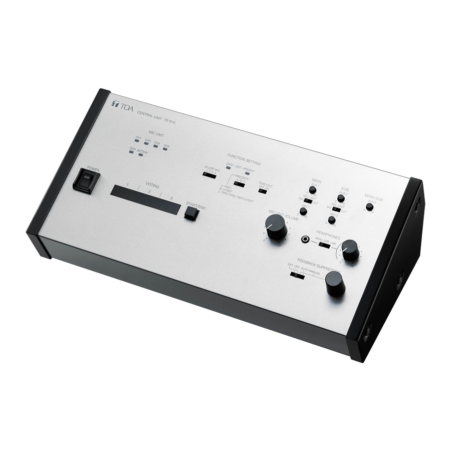
Page 8: Nomenclature And Functions
5. NOMENCLATURE AND FUNCTIONS 5.1. Central Unit TS-910 [Top] 12 13 15 16 1. Power switch 7. AUX 1 input volume control Setting this switch to the ON position causes the Adjusts the input signal level of the AUX 1 Input Power indicator to light. - Page 9 11. MIC 1 input volume control A: First-in-first-out priority B: Last-in-first-out priority Adjusts the input level of the MIC 1 Input Terminal (29) on the rear panel. Signals input to the MIC C: Priority fixed for the first unit, and last-in-first- 1 terminal are output to the base language out priority for all other subsequent units.
- Page 10 [Rear] 25 26 27 28 29 30 31 32 33 34 35 37 38 39 40 41 25. AUX 3 input terminal 32. External control terminal [USB] −20 dB*, 10 kΩ, unbalanced, phone jack. Connects to the external control terminal of a Connect a CD player, tape recorder, or other PC, operation panel or other connected external similar equipment to this terminal.
- Page 11 38. Graphic equalizer output terminal 42. Short circuit indicator −20 dB*, 10 kΩ, unbalanced, RCA jack. Lights when the Expansion unit or its connected Connect this terminal to the graphic equalizer’s cable is shorted. input terminal. 43. Expansion unit I/O terminals 39.
-
Page 12: Chairman Units Ts-911 And Ts-811
5.2. Chairman Units TS-911 and TS-811 [TS-911 Top] [TS-811 Top] PUSH PUSH Note No microphone is supplied with the TS-911/811. 1. Monitor speaker 7. Priority speech key Speech signals from other Conference units and Gives speaking priority to the current speaker. other audio signals from the Central unit are output When this key is used for speech, no other delegate from this speaker. - Page 13 [Bottom] Remove the cover on the bottom side of the unit to expose its setting switches. Note The figure below shows the setting switch labels for both models. [TS-911 setting switch label] [TS-811 setting switch label] RESET RESTORE PRIORITY RESET RESTORE PRIORITY CHIME MUTE...
- Page 14 [Right side] 14. Monitor volume control Adjusts the output volume of the monitor speaker and right-side headphone output. 15. Headphone jack Connect headphones to this jack (mini-jack). Connecting the headphone cuts off the output from the monitor speaker. (Refer to the table below.) Model Output signal...
- Page 15 [Rear] 18. Communication cable connection terminal Connects to the TS-919B4 or TS-919B1 Bridge unit with a CAT-5 LAN cable.
-
Page 16: Delegate Units Ts-912 And Ts-812
5.3. Delegate Units TS-912 and TS-812 [TS-912 Top] [TS-812 Top] PUSH PUSH Note No microphone is supplied with the TS-912/812. 1. Monitor speaker 4. Voting keys (TS-912 only) Speech signals from other Conference units and Use these keys to start, end, and cast voting. The other audio signals from the Central unit are output voting status indicator is provided on each key. - Page 17 [Bottom] Remove the cover on the bottom side of the unit to expose its setting switches. Note The figure below shows the setting switch label. NOT USE UNIT ID 8. Unit address number setting switch Set the unit address number (001 – 192), taking Set a numeral for the ones place and tens place.
- Page 18 [Left side] 12. Headphone volume control Adjusts the output volume of the left-side headphone output. 10 12 [Rear] 13. Communication cable connection terminal Connects to the TS-919B4 or TS-919B1 Bridge unit with a CAT-5 LAN cable.
-
Page 19: Expansion Unit Ts-918
5.4. Expansion Unit TS-918 [Front] 1. Power indicator 2. Connection status indicators Lights when connecting the supplied AC adapter to The corresponding LINE indicator lights when the the DC inlet (5). TS-919B4 or TS-919B1 Bridge unit is connected to the Bridge unit connection terminal (6) and power is supplied to it. -
Page 20: Bridge Unit (4-Conference Unit Connection Type) Ts-919B4
5.5. Bridge Unit (4-Conference unit connection type) TS-919B4 [Front] 1. Connection status indicators The corresponding LINE indicator lights when the Conference unit is connected to the Conference unit connection terminal (3) BRIDGE UNIT TS-919B4 and power is supplied to it. EXPANSION BRIDGE [Bottom]... -
Page 21: System Connection Examples
6. SYSTEM CONNECTION EXAMPLES External equipment connections For base language Amplifier Speaker For translation language Recording unit Graphic equalizer For base and translation languages Central unit TS-910 Bridge unit (1-Conference unit connection type) Expansion unit TS-918 AC adapter Bridge unit (supplied with (4-Conference unit connection type) the TS-910) -
Page 22: Conference Unit Connection
7. CONFERENCE UNIT CONNECTION When connecting the Conference units to the Central unit, the Expansion unit and the Bridge unit must be installed between them. Central unit TS-910 Bridge unit Expansion unit TS-918 TS-919B1/919B4 BRIDGE UNIT TS-919B1 EXPANSION BRIDGE Coaxial cable Conference unit LAN cable (CAT-5) TS-911/912/811/812... - Page 23 7.1.2. Connecting 3 or 4 Expansion units Use the YW-1024 Distributor (4-branch distribution). Connection of 3 Expansion units will leave one of the four terminals idle, however no problems will result. Expansion unit TS-918 Central unit TS-910 Expansion unit TS-918 Distributor YW-1024 Expansion unit TS-918 (4 branches)
-
Page 24: Expansion Unit, Bridge Unit, And Conference Unit Connections
7.2. Expansion unit, Bridge Unit, and Conference Unit Connections Bridge unit When connecting the Expansion unit to the Expansion unit TS-918 TS-919B1/919B4 Conference Unit, the Bridge unit must be installed between the two. BRIDGE UNIT TS-919B1 EXPANSION BRIDGE LAN cable (CAT-5) Conference unit TS-911/912/811/812 The Expansion unit is equipped with 3 Bridge unit connection terminals. - Page 25 7.2.2. Bridge unit TS-919B4 connection Note Bridge unit The Bridge unit may have any TS-919B4 idle terminal among the conference unit connection terminals 1 – 4. BRIDGE UNIT TS-919B4 EXPANSION BRIDGE From Expansion unit TS-918 or To Bridge unit Bridge unit TS-919B1/919B4 TS-919B1/919B4 LAN cable (CAT-5) Conference unit...
- Page 26 7.2.4. Connecting 8 Conference units to one of the Expansion unit’s terminals Bridge unit TS-919B4 BRIDGE UNIT TS-919B4 BRIDGE UNIT TS-919B4 Expansion unit TS-918 EXPANSION BRIDGE EXPANSION BRIDGE Coaxial cable Conference unit TS-911/912/811/812 LAN cable (CAT-5) Only in this case, use this terminal for connection of the 8th unit.
-
Page 27: Wiring
• There is restriction on the number of the Bridge units that can be connected to one of the Expansion unit’s Bridge unit connection terminals. (Refer to p. 25.) Bridge unit Bridge unit TS-919B4 TS-919B1 BRIDGE UNIT TS-919B1 BRIDGE UNIT TS-919B4 BRIDGE UNIT TS-919B4... -
Page 28: Using Wired Microphones And Sound Source Equipment
[When using no Distributor (Maximum cable distance: 200 m)] Distance between the Central unit and Expansion unit: 100 m max. Distance between the Expansion unit and each Conference unit: 100 m max. Distance between the Central unit and each Conference unit: 200 m max. -
Page 29: Sound Source Equipment Use
8.2. Sound source equipment use Connect sound source equipment to the Central unit's AUX input and adjust its volume with the corresponding AUX input volume control. AUX 1, AUX 2, or AUX 3 input volume control Sound source Central unit TS-910 equipment (Top panel) Line output... -
Page 30: Conference Unit Installation And Settings
10. CONFERENCE UNIT INSTALLATION AND SETTINGS Step 1. Use a screwdriver to set the Unit (Inside of the cover) address number setting switch Conference unit located on the unit’s bottom side. NOT USE (bottom side) Hundreds digit Set a numeral for the ones place and tens place. -
Page 31: Rack Mounting
Screws removed in Step 1 (6 screws) Fiber washer (supplied with the MB-TS900) Rack mounting screw 5 x 12 (supplied with the MB-TS900) Note Supplied 5 x 12 rack mounting screws are designed specifically for TOA's equipment rack. Do not use them for other rack mounting. -
Page 32: Mounting The Expansion Unit On A Rack
11.2. Mounting the Expansion Unit on a Rack • Use the optional MB-15B-BK hardware set when mounting a single unit. Remove 8 screws located on both sides of the unit, then attach the optional hardware as shown below. 3 x 8 tapping screw* Component parts and accessories of MB-15B-BK 3 x 14 tapping screw*... -
Page 33: Installation Status Confirmation
12. INSTALLATION STATUS CONFIRMATION Installation status for the Expansion unit, Bridge unit, and Conference units can be checked from the Central unit. Confirm their installation status after completing installation and connection. Note None of the unit's functions can be used while in installation status confirmation mode, except Priority Speech initiated from the Chairman unit. -
Page 34: Signal Flow Diagram Inside The Central Unit
13. SIGNAL FLOW DIAGRAM INSIDE THE CENTRAL UNIT Translation language Base language LINE REC OUT MIC 1 input AUX 1 input MIC 2 input Inter- locking AUX 2 input AUX 3 input AUX 3 output Mix/Cut switch (for base language) Audio signal from Conference units Microphone... -
Page 35: Function Settings
14. FUNCTION SETTINGS 14.1. Setting the Maximum Number of Simultaneous Speakers Using the Simultaneous Speaker No. Setting switch on the TS- 910 Central Unit, set the maximum total number of Conference units that can simultaneously initiate speech. Set the switch to [1], [2], [3], or [4] depending on the type of the conference. -
Page 36: Mic-Off Function
14.2.3. Mode C: Priority fixed for first-enabled unit, and last-in/first-out priority for all subsequent units The first-enabled Conference unit is given fixed speech priority until its Talk key is pressed again. All subsequent Talk key-pressed units are given last-in/first-out priority, as in Mode B. •... -
Page 37: Microphone Mix/Cut Switch Settings
15. MICROPHONE MIX/CUT SWITCH SETTINGS Whether to output voice signals from Conference units to the base or translation language channel can be determined by setting the Microphone Mix/ Cut switch on the TS-910 Central unit. Outputs for individual inputs (MIC 1 – 2, and AUX 1 –... -
Page 38: Operation
16. OPERATION 16.1. Initiating Speech Step 1. Press the Talk key on the Conference unit. PUSH The Speech indicator and Microphone In-Use indicator light, placing the unit in speech mode. No sound is output from the monitor Speech indicator speaker while both indicators... -
Page 39: Initiating Priority Speech (Ts-911 And Ts-811 Only)
16.2. Initiating Priority Speech (TS-911 and TS-811 only) The Chairman unit features the function that allows its speech to take precedence over that of the Delegate unit. The Chairman unit's speech is prior to the AUX 1, AUX 2, AUX 3, MIC 1, and MIC 2 inputs. The priority speech method can be determined by the Priority speech key operation setting switch built in the Chairman unit’s bottom. - Page 40 16.2.2. When the Priority Speech key is set to ALT type Step 1. Press the Priority Speech key. Both the Speech indicator and the Microphone PUSH In-Use indicator light, placing the unit in priority speech mode. No sound is output from the monitor speaker while both indicators are continuously lit.
-
Page 41: Voting (Ts-911 And Ts-912 Only)
16.3. Voting (TS-911 and TS-912 only) Voting can be started and terminated from the Central unit or the Chairman unit. To perform this operation from the Chairman unit, set the Voting activation setting switch to ON as shown in the figure. Chairman unit's bottom RESET RESTORE... -
Page 42: If Acoustic Feedback Occurs
Step 3. Terminate voting. (For the Chairman unit) Again hold down the Voting Start/End button on the Central unit for 1 second or more or alternatively the Chairman unit’s Talk key. Voting operations from the Conference units are confirmed PRIORITY TALK and Voting Status indicators [1] through [3] go out. -
Page 43: Using An External Graphic Equalizer
17.1.2. Using in manual operation mode (MANUAL mode) If acoustic feedback does not stop even using the FBS function in automatic operation mode, follow the procedure below to search the frequency that caused feedback, then suppress the feedback. Step 1. Set the Feedback suppressor switch to the MANUAL position. -
Page 44: If A Failure Is Detected
18. IF A FAILURE IS DETECTED 18.1. Chairman Unit TS-911/811 and Delegate Unit TS-912/812 Symptom Cause and Points to Check Remedy Cannot turn ON power. Both the Central unit and the Expansion Switch on the Central unit’s power and unit are not powered up. power up the Expansion unit through the AC adapter. -
Page 45: Central Unit Ts-910
18.2. Central Unit TS-910 Symptom Cause and Points to Check Remedy Cannot switch ON the Power cord or DC plug not connected. Correctly connect the power cord and power. DC plug supplied with the Central unit. (Refer to the “SYSTEM CONNECTION EXAMPLES”... -
Page 46: Specifications
19. SPECIFICATIONS 19.1. Central Unit TS-910 Power Source 100 – 240 V AC, 50/60 Hz (use of the supplied AC adapter) Power Consumption 72 W Current Consumption Max. 3 A DC (when 24 V DC is supplied from the supplied AC adapter) Carrier Frequency Reception: Audio channel 1:... -
Page 47: Chairman Unit Ts-911, Delegate Unit Ts-912
AC adapter* (DC cord: 1.8 m or 5.91 ft, Detachable AC cord: 2 m or 6.56 ft) ..1 * Not supplied with the TS-918 (KR). For the usable power supply cord and AC adapter, consult your nearest TOA dealer. 19.2. Chairman Unit TS-911, Delegate Unit TS-912 Model No. -
Page 48: Chairman Unit Ts-811, Delegate Unit Ts-812
19.3. Chairman Unit TS-811, Delegate Unit TS-812 Model No. TS-811 TS-812 Power Source 24 V DC (supplied from the optional TS-918 Expansion unit) Current Consumption Max. 60 mA Modulation Method Frequency modulation Carrier Frequency Transmission: Audio channel 1: 7.35 MHz Audio channel 2: 8.10 MHz Audio channel 3: 8.55 MHz Audio channel 4: 9.15 MHz... -
Page 49: Expansion Unit Ts-918
BNC plug-to BNC plug cord (50 cm or 1.64 ft) ............1 * Not supplied with the TS-918 (KR). For the usable power supply cord and AC adapter, consult your nearest TOA dealer. 19.6. Bridge Unit TS-919B1, TS-919B4 Model No. -
Page 50: Distributor Yw-1022 (2-Branch Distributor), Yw-1024 (4-Branch Distributor)
19.7. Distributor YW-1022 (2-branch distributor), YW-1024 (4-branch distributor) Model No. YW-1022 YW-1024 Frequency Range 1.6 – 1000 MHz (excluding 50 – 70 MHz) Distribution Loss 4.5 dB ±3 dB (between the Mixing 8.5 dB ±3 dB (between the Mixing and each Distribution terminals) and each Distribution terminals) Input/Output Impedance 75 Ω... -
Page 51: Rack Joint Bracket Mb-15B-J
19.10. Rack Joint Bracket MB-15B-J Finish Rack mounting bracket: Surface-treated steel plate, black, paint, 30% gloss Coupler: Steel plate, nickel plating Weight 120 g (0.26 lb) Set Composition Mounting bracket ..2, Coupler ..2 Note: The design and specifications are subject to change without notice for improvement. •... - Page 52 Traceability Information for Europe Manufacturer: Authorized representative: TOA Corporation TOA Electronics Europe GmbH 7-2-1, Minatojima-Nakamachi, Chuo-ku, Kobe, Hyogo, Suederstrasse 282, 20537 Hamburg, Japan Germany URL: https://www.toa.jp/ 133-07-00007-05...
Need help?
Do you have a question about the TS-910 Series and is the answer not in the manual?
Questions and answers