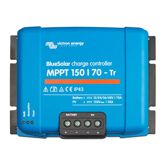
Victron energy BlueSolar MPPT 150/70 User Manual
Charge controller
Hide thumbs
Also See for BlueSolar MPPT 150/70:
- Manual (146 pages) ,
- Owner's manual (154 pages) ,
- Manual (77 pages)
Table of Contents
Advertisement
Advertisement
Table of Contents

Summary of Contents for Victron energy BlueSolar MPPT 150/70
- Page 1 Manual BlueSolar charge controller MPPT 150/70...
- Page 3 DESCRIBED HERE IN. Victron Energy B.V. reserves the right to revise and improve its products as it sees fit. This publication describes the state of this product at the time of its publication and may not reflect the product at all...
- Page 5 1. PRODUCT INTRODUCTION Charge current up to 70 A and PV voltage up to 150 V The BlueSolar 150/70-MPPT charge controller is able to charge a lower nominal-voltage battery from a higher nominal voltage PV array. The controller will automatically adjust to a 12, 24, or 48 V nominal battery voltage. Ultra fast Maximum Power Point Tracking (MPPT) Especially in case of a clouded sky, when light intensity is changing continuously, an ultra fast MPPT controller will improve energy harvest by up to 30% compared to PWM charge controllers and by up to 10%...
- Page 6 At a voltage >75 V, particularly with regard to the open circuit voltage of the PV array, the solar system must be installed according to protection class II. A chassis grounding point is located on the outside of the product. If it can be assumed that the grounding protection is damaged, the product should be taken out of operation and prevented from accidentally being put into operation again;...
- Page 7 Table 1 below gives some examples of battery cable cross sections calculated with formula (5). (in this case I and V in formula (5) are the output current and output voltage of the charge controller) 12V system (solar array up to 1000W) Power loss in Length 2x1,5 m Length 2x2,5 m...
- Page 8 12V system (solar array up to 1000W) Power loss Solar array Solar array Length 2x5 meter Length 2x10 meter Length 2x20 meter in PV cables MPP-voltage MPP-current α Max 50A Not recommended Not recommended Not recommended Not recommended 0,75 24V system (solar array up to 2000W) Power loss Solar array Solar array...
- Page 9 The CAN bus on this charger is not galvanically isolated. The CAN bus is referenced to the minus battery connection. The CAN bus interface will be referenced to ground if the minus pole of the battery is grounded. In case of a positive grounded system, a CAN isolation module will be needed to reference the CAN bus interface to ground.
- Page 10 4. POWERING UP 4.1 Connecting the battery Close the connection to the battery, but DO NOT connect the solar array. All the icons of the display will now light up: This is followed by the software version: In this case the Software-version is 1.1.6 Blinking: After the software-version has been displayed, the Nominal battery voltage...
- Page 11 4.3 Charge algorithm 4.3.1. Overview Several preset charge curves and one user adjustable curve are available, see table below. The DEFAULT-setting is algorithm nr 2. Make sure the charge algorithm is correct for the battery-type that must be charged. If necessary, contact the battery supplier for the appropriate battery-settings.
- Page 12 4.3.4. Other charge algorithm related settings Absorption time: default 8 hours Temperature compensation: default -2,7 mV/° C per cell (-65 mV/° C for a 48V lead-acid battery) Equalisation: Some manufacturers of VRLA (Valve Regulated Lead-Acid: i.e. Gel or AGM) batteries recommend a short equalization period, most do not.
- Page 13 5.2 SETUP MENU parameter details a. To enter the SETUP Menu, press and hold the SETUP-button during 3 seconds. The “Menu” icon will light up. b. Press the "-" or "+" button to scroll. Table 3 below lists in order off appearance all parameters which can be adjusted when pressing the "-"...
- Page 14 1) Press SELECT for 4 seconds to reset to original factory settings. After 4 seconds the charger will re-boot. 2).These values can ONLY be changed for the battery number 8 (USr) (User-defined battery). The values in the table are for a 48V-battery. 3) When Automatic equalisation is “ON”, the absorption charge will be followed by a voltage limited constant current period (see table 3).
- Page 15 7. TROUBLESHOOTING With the procedures below, most errors can be quickly identified. If an error cannot be resolved, please refer to your Victron Energy supplier. Error Problem Cause / Solution nr. on display n. a. The LCD does not The internal power supply used for powering the converter and the light up (no backlight, backlight is derived from either the solar-array or the battery.
- Page 16 output current the air inlet and outlet holes of the charger cabinet. Err 18 Controller over-current This error will auto-reset. Disconnect the charge controller from all power-sources, wait 3 minutes, and power up again. If the error persists the charge controller is probably faulty. Err 19 Reverse current This error will auto-reset.
- Page 17 8. SPECIFICATIONS BlueSolar charge controller MPPT 150/70 Nominal battery voltage 12 / 24 / 36 / 48V Auto Select Rated charge current 70A @ 40° C (104° F) Maximum solar array input power 12V: 1000W / 24V: 2000W / 36V: 3000W / 48V: 4000W Maximum PV open circuit voltage 150V Minimum PV voltage...
- Page 18 10. OVERVIEW CONNECTIONS flatcable 1 Temperature sense 2. Voltage sense 3. Battery 4. Solar array 5.Ground connection (PE) 6. 2x CAN Bus RJ45 7. Programmable relay...
- Page 21 Serial number: Version : 00 Date : 08 June 2012 Victron Energy B.V. De Paal 35 | 1351 JG Almere PO Box 50016 | 1305 AA Almere | The Netherlands General phone +31 (0)36 535 97 00 Customer support desk...


Need help?
Do you have a question about the BlueSolar MPPT 150/70 and is the answer not in the manual?
Questions and answers