Table of Contents
Advertisement
Quick Links
Advertisement
Table of Contents

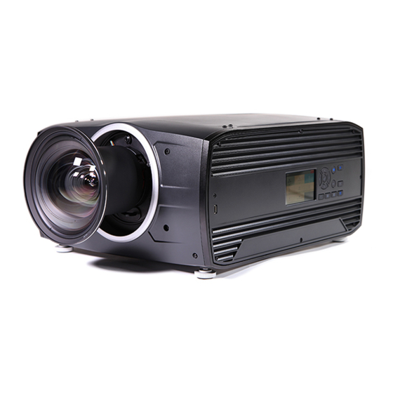
Related Manuals for Barco Balder


Summary of Contents for Barco Balder
- Page 1 Balder Installation Manual 601–0442/00 13/09/2017...
- Page 2 Barco Fredrikstad AS Habornveien 53, N-1630 Gamle Fredrikstad, Norway Phone: +47 6930 4550 Fax: +47 6930 4580 Support: Support.fre@barco.com Visit us at the web: www.barco.com Printed in Norway...
-
Page 3: Disposal Information
Changes Barco provides this manual ’as is’ without warranty of any kind, either expressed or implied, including but not limited to the implied war- ranties or merchantability and fitness for a particular purpose. Barco may make improvements and/or changes to the product(s) and/or the program(s) described in this publication at any time without notice. -
Page 4: Software License Agreement
The period of guarantee begins on the date of transfer of risks, in the case of special systems and software on the date of commissioning, at latest 30 days after the transfer of risks. In the event of justified notice of complaint, Barco can repair the fault or provide a replacement at its own discretion within an appropriate period. -
Page 5: Table Of Contents
Product..........................49 601–0442 BALDER 13/09/2017... - Page 6 HD in function of the lens Throw Ratio (TR) ..................54 601–0442 BALDER 13/09/2017...
-
Page 7: Safety
Clarification of the term ’Balder’ used in this document When referring in this manual to the term, ’Balder’, means that the content is applicable for the following products: •... -
Page 8: General Safety Instructions
VOLTAGE ELECTRIC and ELECTRONIC CIRCUITRY and HIGH BRIGHTNESS PROJECTORS) in performing a task, and of mea- sures to minimize the potential risk to themselves or other persons. Only Barco authorized SERVICE PERSONNEL, knowledgeable of such risks, are allowed to perform service functions inside the product enclosure. The term USER and OPERATOR refers to any person other than SERVICE PERSONNEL. -
Page 9: Important Safety Instructions
It is hazardous to operate without lens or lens cap. Lenses or shields shall be changed if they have become visibly damaged, for example with cracks or deep scratches, to such an extent that their effectiveness is impaired. 601–0442 BALDER 13/09/2017... - Page 10 Do not place flammable or combustible materials near the projector! • For the Balder projector the exclusion zone on the lens side within the light beam must be at least 1,0m. • Caution! Hot air is exhausted from the rear vent. Do not place objects that are sensitive to heat nearer than 100 cm (40”) to the exhaust vent.
-
Page 11: Projector Hazard Distances
• Unplug this product from the wall outlet and refer servicing to Barco authorized service personnel or technicians under the following conditions: If liquid has been spilled into the equipment. -
Page 12: Weee Information
It can be disassembled to facilitate proper recycling of it’s individual parts. Consult your dealer or relevant public authority regarding drop-off points for collection of WEEE. For details, please visit the Barco website at: http://www.barco.com/en/ AboutBarco/weee. -
Page 13: Rohs Compliance
(Also called RoHS of Chinese Mainland), the table below lists the names and contents of toxic and/or hazardous substances that Barco’s product may contain. The RoHS of Chinese Mainland is included in the MCV standard of the Ministry of Information Industry of China, in the section “Limit Requirements of toxic substances in Electronic Information Products”. - Page 14 GB/T 26572 X: 表示該有毒有害物質至少在該部件的某一均質材料中的含量超出 GB/T 26572 標準規定的限量要求。 X: Indicates that this toxic or hazardous substance contained in at least one of the homogeneous materials used forth is part is above the limit requirement in GB/T 26572. Image 1-2 601–0442 BALDER 13/09/2017...
- Page 15 X: 表示该有毒有害物质至少在该部件的某一均质材料中的含量超出 GB/T 26572 标准规定的限量要求. X: Indicates that this toxic or hazardous substance contained in at least one of the homogeneous materials used for this part is above the limit requirement in GB/T 26572. 在中国大陆销售的相应电子信息产品(EIP)都必须遵照中国大陆《电子电气产品有害物质限制使用标识要求》标准贴上环保使用期 限(EFUP)标签。Barco产品所采用的EFUP标签(请参阅实例,徽标内部的编号使用于指定产品)基于中国大陆的《电子信息产品环 保使用期限通则》标准。 601–0442 BALDER 13/09/2017...
-
Page 16: Contact Adresses
Chinese Mainland, marked with the Environmental Friendly Use Period (EFUP) logo. The number inside the EFUP logo that Barco uses (please refer to the photo) is based on the “General guidelines of environment-friendly use period of electronic information products”... -
Page 17: Lenses
The electrical connection to the lens motors is via a spring probe contact (pogo) pin array on the bayonet mount. The projector will automatically detect and identify the lens when it is installed. Automatic detection is not available for 3rd party lenses. 601–0442 BALDER 13/09/2017... -
Page 18: Replace A Lens
Replace a lens Lens lever The Balder lens mount and lens lever is designed to prevent damage to the lens board while providing an easy and stable lens change procedure. The lens lever, located at the bottom of the lens mount (ref. ) slides between two positions, far left (default position — unlocked) and far right (locked). - Page 19 2. Use the other hand to slide the lens release lever to the far left position. 3. Pull the lens straight out of the projector lens mount. 4. Replace with another lens, or install the projector lens cap. Image 2-4 601–0442 BALDER 13/09/2017...
-
Page 20: Lens Shift
See the procedure explained below to perform this. ARNING This procedure must be performed ONLY by Barco trained service personnel. Opening the unit may cause a risk of electrical shock, and exposure to high intensity laser beam. -
Page 21: Adjust Zoom And Focus
All four locking positions must be used to achieve a sufficient locking. Image 2-7 7. Reinstall the front cover. 8. Reinstall the Projector lens. Adjust zoom and focus General Zoom controls the size of the projected image. 601–0442 BALDER 13/09/2017... -
Page 22: Adjust Iris
Iris control is, as for the zoom and focus control, motorized, and is operated by the remote control or local keypad. Iris is only available for units with COLOR type colorwheel. To enter Iris control, enter the menu Home/Installation/Lens /Iris Image 2-8 Use the arrow keys to adjust Iris until preferred rendering is obtained. 601–0442 BALDER 13/09/2017... -
Page 23: Physical Installation
3. PHYSICAL INSTALLATION About This chapter describes the physical conditions and procedures required when installing the Balder projector. It also describes the outlines and some of the considerations that should be taken in to account when designing and setting up the installation. -
Page 24: Initial Inspection
Upon receipt of the projector, we recommend that customers inspect the projector for any signs of damage that may have occurred in transit. If damage is found, file a claim with the shipping carrier immediately. Notify the Barco Sales and Service office, or your preferred Barco agent, of the damage as soon as possible. -
Page 25: Positioning The Projector
EMC Considerations The Balder Projector is a EMC class A product, that may cause interference when used in residential areas. Special measures to reduce electromagnetic emissions to prevent interference to the reception of radio and television broadcasts may be needed. -
Page 26: Adjustable Feet
5. Go to Main Menu / Test Patterns and select an internal hatch pattern to display on the screen. 6. Adjust the position (height and angle) of the rigging frame until the projected hatch pattern is a level and perfect rectangle. 601–0442 BALDER 13/09/2017... -
Page 27: Projector Safe Attachment Points
Note that there is only this 4 selected attachment points that is approved as anchor points for the unit. Anchorpoints. For attaching to rigging frame or similar. Image 3-3 Item Thread Dimension Max Hole Depth Application 15mm Anchorpoint / Ceiling / Rig Mount 601–0442 BALDER 13/09/2017... -
Page 28: Throw Distance
To solve this the lens plane must be placed parallel with the DMD plane. This can be achieved by turning the lens holder to remove the tilt (or swing) between lens plane and DMD plane (Lp3→Lp4). 601–0442 BALDER 13/09/2017... -
Page 29: Scheimpflug Adjustment Procedure
Preparation 1. Prepare the test area. Barco recommends a projector-screen distance of 2 metres be used for all Scheimpflug adjustments. Verify that the throw ratio of the installed lens matches the requirements of the installation area (projection distance and screen size). - Page 30 Note: This process may cause the other areas of the image to slide out of focus. This is totally normal. Image 3-9 5. Continue adjusting the screws one at a time until the test image is uniformly sharp across all areas of the display. 601–0442 BALDER 13/09/2017...
- Page 31 2 to 6 until the image is correct. 7. Tighten the three set screws in the following order: left (1b), right (2b) and then top (3b). Use a size 6 hex key to do this. 601–0442 BALDER 13/09/2017...
- Page 32 3. Physical Installation 601–0442 BALDER 13/09/2017...
-
Page 33: Getting Started
• DVI-I • Display Port 1.2 • HDMI 2.0 • 3G-SDI • HDBase T 4.1.2.1 DVI-I Specifications Parameter Value Connector DVI-I female digital RGB Signal characteristics DVI 1.0, Digital, TMDS Max. cable length 25 m (24 AWG) 601–0442 BALDER 13/09/2017... -
Page 34: Display Port 1.2
Connector Standard HDMI Signal characteristics Digital, TMDS Max. cable length 15 m (24 AWG) Max. pixel rate 594MHz Max. input data resolution 3840x2160 @60Hz Bit depth 8, 10, 12 bits EDID Supported HDCP Supported Ethernet Audio return 601–0442 BALDER 13/09/2017... -
Page 35: Sdi
4.1.3 Control interfaces About The following control interfaces are available on the projector: • 1x RS-232 (for projector control) • 1x LAN/Ethernet (for projector control • 3x USB-A ports Overview • RS-232 • LAN/Ethernet • USB-A port 601–0442 BALDER 13/09/2017... -
Page 36: Lan/Ethernet
1. Depress and hold the power button on the keypad or remote for four (4) seconds. The Projector is now in cooling down phase. 2. When the projector panel is no longer illuminated, remove the mains power cord from the projector. 601–0442 BALDER 13/09/2017... -
Page 37: Power Modes
Press the OK button to select a menu topic and get more options. Use the numeral keys to enter values, or use the arrow keys to move the barscale up or down. Press MENU again to exit the menu system. 601–0442 BALDER 13/09/2017... -
Page 38: Menu Memory
ENTER 79 ENTER. Changes to values are implemented dynamically. Menu memory The OSD menu remembers the last selected sub–item as long as the projector is running. The menu memory is reset when restarting the projector from standby. 601–0442 BALDER 13/09/2017... -
Page 39: Image Menu
Not all settings are available for all source types. Settings that are not available for the active source will be grayed out and not available for selection. P7 RealColor Advanced functionality for color management. Image / Advanced / P7 RealColor —>White point 601–0442 BALDER 13/09/2017... -
Page 40: Color Mode
Image / Advanced / P7 RealColor —>Mode Allows users to specifying red, green blue, cyan, magenta and yellow color coordinates (x,y) and gain. Current values are presented in the color gamut diagram. Desired values are represented by a dotted line. 601–0442 BALDER 13/09/2017... -
Page 41: Advanced Picture Adjustments
This means that there will be black bars at the side of the picture. All cropping is done dynamically. For best result Barco recommend that you pause the movie on the screen, making sure that any subtitles or text ate visible. Then activate the cropping function from the menu. -
Page 42: Manual Cropping
Then the left and right sides must be adjusted. The value entered here must be equal to the vertical lines removed, multiplied with the aspect ratio, in order to keep the correct correlation between the width and height . Example: removed 200 lines in 16:9 format: 200 x (16/9) = number of lines to remove on each side. 601–0442 BALDER 13/09/2017... -
Page 43: 16:9 To Center Function
How to enter the 16: to center function Home/Image/16:9 to center Image 6-3 Select this function by entering the menu path shown above. Enter the slider switch to enable. The menu will show the status of the function, On of Off. 601–0442 BALDER 13/09/2017... - Page 44 6. Advanced picture adjustments 601–0442 BALDER 13/09/2017...
-
Page 45: Installation Menu
About Installation / Orientation Rotate the image on the imaging device depending on the physical installatin of the unit. There are four installationoptions, as illustrated below: • front/table • front/ceiling • rear/table • rear/ceiling Default: Table Front. 601–0442 BALDER 13/09/2017... -
Page 46: Warp
Image warping is the process of digitally manipulating an image to compensate for the distortion of the screen, typically by non perpendicular alignment of the projector versus the screen. The image will then typically occur as shown inimage 7-4. While an image can be transformed in various ways, pure warping doesn’t affect the colors. 601–0442 BALDER 13/09/2017... -
Page 47: Corners Adjustment
Changes occur dynamically to the image display. How to adjust Warp Enter the Warp menu, Enable the Warp button, and select the corners that must be adjusted. Use the arrow keys to move the corners. When finished, exit the menu. 601–0442 BALDER 13/09/2017... -
Page 48: Warping - Bow
A bow distortion can be adjusted so that a normal image is displayed. Positive adjustments introduce more outside bow distortion. Negative adjustments introduce more inside bow distortion. Image 7-6 Bow distortion How to adjust 1. In the main menu, select Installation → Warp. 601–0442 BALDER 13/09/2017... -
Page 49: Basic Blend
The principle is that the light intensity in the blend zone from each projector will be adjusted individually, so that the rendering on the screen are perceived as from one projector. The blend function can be enabled for both pictures over/under, and pictures side by side. 601–0442 BALDER 13/09/2017... - Page 50 Entering the Blend Adjustment from the Home menu, either by the remote control, or the keypad on the projector.Home/Installa- tion/Blend/Blend ZonesThe menu shown below appears on the OSD. The “Enable” button enables/disables the blend function. The “Show Lines” enables alignment lines on the screen, in order to visualize the overlap/blend zone. 601–0442 BALDER 13/09/2017...
-
Page 51: Illumination
An example can be: If the source is a pc, you may want to hide the menu bar at the bottom of the screen. Illumination About Home/Installation /Illumination/Power Review light source status and adjust (dim) laser power from 0 to 100%. Default: 100% 601–0442 BALDER 13/09/2017... - Page 52 7. Installation menu 601–0442 BALDER 13/09/2017...
-
Page 53: Status Menu
Home / Status / Illumination Shows the current laser power (%) and laser runtime. This is a status menu only. No changes can be made to settings from this menu. Communication About Home / Status / Communication 601–0442 BALDER 13/09/2017... - Page 54 8. Status menu Lists the projector IP address. 601–0442 BALDER 13/09/2017...
-
Page 55: Risk Group 3 Safety
Users definition The Balder projector is intended for persons who have been instructed and trained by Barco authorized personnel to identify energy sources that may cause injury and to take precautions to avoid unintentional contact with or exposure to those energy sources. - Page 56 (RZ) in the theater must be established. This can be done by using physical barrier, like a red rope as illustrated in image 1-2. The restricted area sticker can be replaced by a sticker with only the symbol. 601–0442 BALDER 13/09/2017...
-
Page 57: Hazard Distance For Fully Closed Projection System
PR Projector. Theater (observation area). Restriction Zone PD Projection Distan SW Separation Width. Must be minimum 1 meter. Restriction zone (RZ) based on the HD continued. For this type of setup 3 different HD shall be considered: 601–0442 BALDER 13/09/2017... -
Page 58: Hd In Function Of The Lens Throw Ratio (Tr)
HD versus Throw Ratio Hazard Distance Thermal Acidental Exposure Throw Ra o Image 9-4 Hazard Distance in meters versus Throw ratio of the lens for the Balder projector Graphs shows Hazard Distance in meters versus Throw ratio of the lens 601–0442 BALDER 13/09/2017...
Need help?
Do you have a question about the Balder and is the answer not in the manual?
Questions and answers