
Related Manuals for Barco Loki


Summary of Contents for Barco Loki
- Page 1 Loki Installation Manual ENABLING BRIGHT OUTCOMES...
- Page 2 Barco Fredrikstad AS Habornveien 53, N-1630 Gamle Fredrikstad, Norway Support.fre@barco.com www.barco.com...
- Page 3 Changes Barco provides this manual 'as is' without warranty of any kind, either expressed or implied, including but not limited to the implied warranties or merchantability and fitness for a particular purpose. Barco may make improvements and/or changes to the product(s) and/or the program(s) described in this publication at any time without notice.
- Page 4 Barco. If the purchaser or a third party carries out modifications or repairs on goods delivered by Barco, or if the goods are handled incorrectly, in particular if the systems are operated incorrectly or if, after the transfer of risks, the goods are subject to influences not agreed upon in the contract, all guarantee claims of the purchaser will be rendered invalid.
-
Page 5: Table Of Contents
4 Getting started .........................................39 Projector source and control connections...........................40 4.1.1 Making connections..............................40 4.1.2 Connector specifications ............................40 4.1.2.1 DVI-I ................................40 4.1.2.2 Display Port 1.2 ............................41 4.1.2.3 HDMI 2.0 ..............................41 4.1.2.4 SDI ................................41 4.1.2.5 HDBase T..............................42 4.1.3 Control interfaces................................42 4.1.3.1 RS-232...............................43 601–0445 /05 Loki... - Page 6 7 Advanced picture adjustments ................................71 Cropping the image ..................................72 Preset Crop mode ....................................72 Manual Cropping....................................73 Automatic source cropping................................74 16:9 to center function..................................74 8 Installation menu......................................77 Lens..........................................78 8.1.1 Zoom / Focus ...................................78 8.1.2 Shift......................................78 8.1.3 Shift to center ...................................79 601–0445 /05 Loki...
- Page 7 12.1 General considerations ................................122 12.2 Safety Training provided by the installer........................... 122 12.3 High Brightness Precautions..............................123 12.4 Hazard Distance for fully closed projection system....................125 12.5 HD in function of the lens Throw Ratio (TR) ........................126 601–0445 /05 Loki...
- Page 8 601–0445 /05 Loki...
-
Page 9: Safety
Clarification of the term 'Loki' used in this document When referring in this manual to the the term, 'Loki', means that the content is applicable for the following products: •... -
Page 10: General Considerations
WARNING: Be careful while working with heavy loads WARNING: Mind your fingers while working with heavy loads. Notice on optical radiation from Loki Projector When installing an interchangeable lens with a throw ratio that make the projector become an RG3 unit, (See the chapter “Approved Lenses”... -
Page 11: Important Safety Instructions
HIGH BRIGHTNESS PROJECTORS) in performing a task, and of measures to minimize the potential risk to themselves or other persons. Only Barco authorized SERVICE PERSONNEL, knowledgeable of such risks, are allowed to perform service functions inside the product enclosure. The term USER and OPERATOR refers to any person other than SERVICE PERSONNEL. - Page 12 Do not place flammable or combustible materials near the projector! • For the Loki projector, the exclusion zone on the lens side within the light beam must be at least 1,5m. • Caution! Hot air is exhausted from the rear vent. Do not place objects that are sensitive to heat nearer than 100 cm (40”) to the exhaust vent.
- Page 13 • Unplug this product from the wall outlet and refer servicing to Barco authorized service personnel or technicians under the following conditions: If liquid has been spilled into the equipment.
-
Page 14: Projector Hazard Distances
Caution! Do not stare into beam, RG2 product. No telephone! Do not connect to telephone lines. Loki Warning Label Caution! For North America: With interchangeable lens with throw ratio greater than 2.33, consider hazard For North America, this projector may become RG3 when an interchangeable lens with throw ratio greater than This projector may become RG3 when an interchangeable lens with throw ratio greater than 3.15 is... -
Page 15: Disposal Information
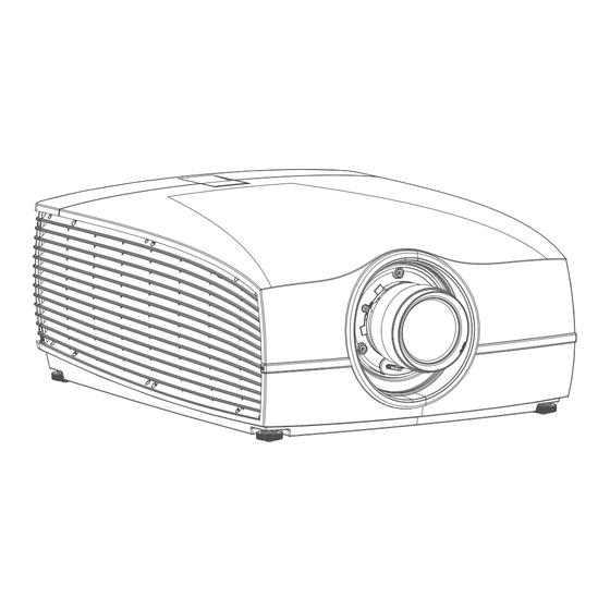
Location of Safety Label EMC Label Warning Label Image 1-1: Loki Projector CAUTION: This product contains chemicals, including lead, known to the State of California to cause birth defects or other reproductive harm. Recycle properly, do not dispose of in ordinary waste! 1.5 Disposal Information... -
Page 16: Turkey Rohs Compliance
Electronic Products” (Also called RoHS of Chinese Mainland), the table below lists the names and contents of toxic and/or hazardous substances that Barco’s product may contain. The RoHS of Chinese Mainland is included in the MCV standard of the Ministry of Information Industry of China, in the section “Limit Requirements of toxic substances in Electronic Information Products”. -
Page 17: Taiwan Rohs Compliance
Chinese Mainland, marked with the Environmental Friendly Use Period (EFUP) logo. The number inside the EFUP logo that Barco uses (please refer to the photo) is based on the “General guidelines of environment-friendly use period of electronic information products”... -
Page 18: Contact Information
公司名稱 (Company Name):巴可股份有限公司 地址 (Address):新北市板橋區新站路16號33樓 傳真 (Fax):02-7715 0298 電話 (Tel):02-7715 0299 E-mail:service.taiwan@barco.com Importers contact information To find your local importer, contact Barco directly or one of Barco's regional offices via the contact information given on Barco's web site, www.barco.com. 601–0445 /05 Loki... -
Page 19: Product Info
Safety Contact information Norway factory Barco Fredrikstad as Habornveien 53, N1630 Gamle Fredrikstad, Norway Phone: +476930 4550 Support:Support.fre@barco.com 1.10 Product Info Product info Image 1-2 product name 產品名稱: projector 投影機 model 型號: GP6 1.11 Statement EN55032/CISPR32 Class A MME (MultiMedia Equipment) Warning : This equipment is compliant with Class A of CISPR 32. - Page 20 Safety 601–0445 /05 Loki...
-
Page 21: Lenses
Lenses About Overview • Approved Lenses • Lens range • Replace a lens • Lens calibration 601–0445 /05 Loki... -
Page 22: Approved Lenses
EN46 EN41 Image 2-1 Description Weight Name Part number FLD+ Lens 1.7 - 2.5 : 1 1.7 - 2.5 : 1 R9801216 2.54 kg (EN41) FLD+ Lens 0.8 : 1 (EN42) 0.8 : 1 R9801226 2.7 kg 601–0445 /05 Loki... -
Page 23: Replace A Lens
2.3 Replace a lens Lens lever The Loki lens mount and lens lever is designed to prevent damage to the lens board while providing an easy and stable lens change procedure. The lens lever, located at the bottom of the lens mount (ref. ) slides between two positions, far left (default position —... - Page 24 Support the lens with one hand. Use the other hand to slide the lens release lever to the far left position.. Pull the lens straight out of the projector lens mount. Replace with another lens, or install the projector lens cap. 601–0445 /05 Loki...
-
Page 25: Lens Calibration
Image 2-5: Focus, iris and zoom need to be calibrated. Select the first item to be calibrated, and confirm with enter on the remote or the keypad. When the calibration is OK, the question mark changes to &enter Repeat for each calibration item. 601–0445 /05 Loki... - Page 26 Lenses Image 2-6: Image 2-7: All calibrations performed and OK. 601–0445 /05 Loki...
-
Page 27: Physical Installation
Physical installation About This chapter describes the physical conditions and procedures required when installing the Loki as well as outlines some of the considerations you should take into account when designing and setting up the projector installation. Each projector installation is unique, and as such the information in this chapter is only provided as a guideline. -
Page 28: Installation Process
/ hour AutoDim function The Loki AutoDim function is integrated in the projector firmware. The projector continually senses and calculates the ambient temperature in the installation location and will, when necessary, automatically dim the light output if the projector is operating in the extreme ends of the recommended ambient environmental conditions, as illustrated in the graph below. - Page 29 Image 3-1 Mains power requirements Projector Power requirements Loki 100 — 240 V, 50 — 60 Hz To protect operating personnel, the National Electrical Manufacturers Association (NEMA) recommends that the instrument panel and cabinet be grounded. In no event shall this projector be operated without an adequate cabinet ground connection.
-
Page 30: Initial Inspection
Upon receipt of the projector, we recommend that customers inspect the projector for any signs of damage that may have occurred in transit. If damage is found, file a claim with the shipping carrier immediately. Notify the Barco Sales and Service office, or your preferred Barco agent, of the damage as soon as possible. Box Contents Your projector box should contain the following: •... -
Page 31: Mounting The Projector, General Considerations
Installation and use of the Rigging Frame are described in document R5906768 F90 Multifunctional Frame — Installation Manual. The threaded hole in the lower back end of the projector is NOT suitable for lifting or other heavy operations. Only for adjustment purposes. 601–0445 /05 Loki... -
Page 32: Projector Safe Attachment Points
The projector has four anchoring points (ref 1, image 4-5) that can be used with the rigging frame and projector installation. There are an additional 9 fastening points (ref 2 and 3, image 4-5) that can used for attaching light weight accessories and other miscellaneous equipment. See table below for more information. 601–0445 /05 Loki... -
Page 33: Throw Distance
0.99:1, then the throw distance (D) will be 2.38 meters. Calculation: 2.4 x 0.99 = 2.38 The following graphs illustrate the image size (W) and projection distance (D) for each of the projector lenses. Tolerances are typically +/- 5% due to optical (lens) variation. 601–0445 /05 Loki... -
Page 34: Scheimpflug (Boresight) Adjustment
DMD plane. This can be achieved by turning the lens holder to remove the tilt (or swing) between lens plane and DMD plane (Lp3→Lp4). Image 3-7: Scheimpflug principle 601–0445 /05 Loki... -
Page 35: Scheimpflug Adjustment Procedure
Scheimpflug adjustment points Scheimpflug adjustment points are located on the lens mount. The Loki has three (3) set screws and three (3) adjustment screws. When to apply Scheimpflug? Scheimpflug correction procedures may only be carried out by suitably trained and experienced technicians. - Page 36 Adjust the top Scheimpflug adjustment screw (reference 3) until the test image in the bottom half of the screen is in focus. Use a size 4 hex key to do this. Note: This process may cause the other areas of the image to slide out of focus. This is totally normal. 601–0445 /05 Loki...
- Page 37 If there are any deviations to sharpness, repeat steps 2 to 6 until the image is correct. Tighten the three set screws in the following order: left (1b), right (2b) and then top (3b). Use a size 6 hex key to do this. 601–0445 /05 Loki...
- Page 38 Physical installation 601–0445 /05 Loki...
-
Page 39: Getting Started
This chapter describes how to set up and optimize your projector setup when the physical installation process is complete. Overview • Projector source and control connections • Power up the projector • Power down the projector • Power mode transitions • Power modes • Customize projector settings • User interface 601–0445 /05 Loki... -
Page 40: Projector Source And Control Connections
330 MHz (dual link), 165 Mhz (single link) Scan format Progressive Max. input data resolution 1920x1200 60Hz (Single link), 2560x1600 60Hz (Dual Link), 1920x1200 120 Hz (Dual Link), 1920x2400 @60Hz Bit depth 8 bit EDID Supported HDCP Supported 601–0445 /05 Loki... -
Page 41: Display Port 1.2
Supported Ethernet Audio return HDCP Supported 4.1.2.4 SDI Specifications Parameter 12G-SDI 3G-SDI Standard SMPTE ST-2082-1 and ST-2082-10 SMPTE 424M-2006 10bit level A standards Connector Samtec BNC7T-J-P-HN-RA-BH1 1x) BNC 75 ohm type IEC 60169-8, Amendment 2 1997, A 601–0445 /05 Loki... -
Page 42: Control Interfaces
Not Supported LEDs - HD Base Status Operation: Green, Left Link/Mode: Yellow, Right 4.1.3 Control interfaces About This section gives information about interfaces used to control the projector. Overview • RS-232 • LAN/Ethernet • USB-A port • 601–0445 /05 Loki... -
Page 43: Lan/Ethernet
You can use the DMX input port to connect a DMX device (DMX console) to the projector. This way you can control the projector from that DMX device (console). The DMX output port can be connected with the next device in the loop. Description Earth Cold Return - (or not used) Return + (or not used) 601–0445 /05 Loki... -
Page 44: Power Up The Projector
4.4 Power mode transitions 4.4.1 General Transition Diagram This diagram shows all modes available on the projector (unplug, ON, READY, ECO), and the actions necessary to change mode. 601–0445 /05 Loki... -
Page 45: Power On Projector
The projector will power down through a cool down phase. The Power on/off button will BLINK WHITE during the transition from ON to READY. Once the projector is in READY, thePower on/off button will be lit WHITE. 601–0445 /05 Loki... -
Page 46: Going From Ready To Eco Standby
The LAN cable must be connected when the projector enter the ECO mode, in order to obtain the Wake on LAN function. 4.5 Power modes General The table below details the Loki power modes. Description Mode Normal Projector is booted up and the light source is on... -
Page 47: On Screen Display (Osd)
ENTER 79 ENTER. Changes to values are implemented dynamically. Menu memory The OSD menu remembers the last selected sub–item as long as the projector is running. The menu memory is reset when restarting the projector from standby. 601–0445 /05 Loki... - Page 48 Getting started 601–0445 /05 Loki...
-
Page 49: Source Menu
By navigate through the Home/Source menu, it will be visible also on the OSD. By using the shortcut key, the menu occurs only on the LCD display. Overview • Connector selection • Connector settings • Using dual inputs 601–0445 /05 Loki... -
Page 50: Connector Selection
Identification Data (EDID). When entering the menu for each input connector, you can change the following: • Color Space • Signal Range • EDID How to configure a connector Press Menu to activate the menus and select Source. 601–0445 /05 Loki... - Page 51 To force a limit on the used signal range, select one of the available signal ranges. • To set a video timing other than the one native for the connector, select one of the options under EDID. Note: You cannot change the EDID for SDI connectors. 601–0445 /05 Loki...
-
Page 52: Using Dual Inputs
Change the EDID for each channel to the correct value. See chapter “Connector Settings” for EDID setup. Dual Sequential Input1 3840 3840 1920 1920 2400 2400 2400 2400 3840 Dual Column Input1 Dual Column Input 2 Dual Sequential Input 2 Image 5-5: Dual Column Setup Image 5-6: Dual sequential setup. 601–0445 /05 Loki... -
Page 53: Image Menu
The operation of the menus can be done with both the remote control or the arrows on the keypad. It is also possible to switch between the different adjustments by using the up and down arrows, instead of exit one menu and then enter the next one. Image 6-1 601–0445 /05 Loki... - Page 54 When entering any of these menus from the Keypad, the screen below will show up in the LCD panel. Use the arrow keys to select and adjust the values. Image 6-2: Image sub menu visible on the LCD. 601–0445 /05 Loki...
-
Page 55: Contrast
Image 6-4: Brightness OSD menu 6.3 Saturation About Image / Saturation Saturation levels impact on the white levels and the intensity of the color display; the higher the value, the more vivid the color display will be. 601–0445 /05 Loki... -
Page 56: Sharpness
Gamma compensation, or gamma correction, is a way of adjusting the signal input to light output characteristics of a display or projector in order to suit the eye’s sensitivity to different light levels and to compensate for non-linearities in displays. Without gamma compensation, images may look too dark or too 601–0445 /05 Loki... -
Page 57: Digital Zoom Shift
Enter the menu shown below, either via the Remote control or the keypad. The combined menu is showed below. The symbols on the lower part of the menu are symbols showing how to operate the keypad / remote control for the digital shift / digital zoom modes.. Image 6-9 601–0445 /05 Loki... -
Page 58: Digital Zoom
The numbers on the right side of the menu represent the “new” resolution of the picture (assuming that the whole picture should be visible) in pixels. The aspect ratio will not be affected by the zoom function. This function can also be used in combination with digital shift. Image 6-10: Originally picture, not digitally zoomed 601–0445 /05 Loki... -
Page 59: Digital Shift
The numbers on the right side of the menu represent the movement (shift) of the picture in pixels referred to the “no shift” position. Positive numbers are shift right/down, and negative numbers are shift left/up. This function can also be used in combination with the Digital zoom function. 601–0445 /05 Loki... -
Page 60: Advanced Image Adjustments
The selection of the presets will vary, depending on the projector type, and the color wheel installed. How to choose one of the P7 presets In the main menu, select Image → Advanced → P7 Realcolor. 601–0445 /05 Loki... - Page 61 Note: When choosing one of the presets, All other options in the P7 menu are disabled. How to set custom P7 values In the main menu, select Image → Advanced → P7 Realcolor. The P7 menu is displayed. 601–0445 /05 Loki...
-
Page 62: Edit The Realcolor Presets
The edited presets can be reset to the original values by enter the Reset button. There is also a possibility to copy the values to the custom preset. To reset the values in Custom presets, enter the “Reset to native” button when in Custom mode 601–0445 /05 Loki... -
Page 63: Output Resolution 4K
6.7.3 Output resolution 4K About With this function, the projector output resolution can be changed between 4K UHD resolution and WQXGA resolution. Refer to the chapter “Projector source and control connections” regarding use of input sources in 4K mode. 601–0445 /05 Loki... -
Page 64: Smear Reduction
Changes the color rendering, by adding secondary colors. This has the effect of increasing the color intensity, and by that also the perceived light intensity. Enter the menu, and select the option that give the best result 601–0445 /05 Loki... - Page 65 SRP Half Plus BSI Native Video SRP Off Native Video Graphics SRP Half WQXGA@120Hz / 4K mode Native SRP Half Plus Native Video Native BSI (Black Sub Frame Insertion) Video 4K @ 60Hz Graphics SRP Half BSI Native 601–0445 /05 Loki...
-
Page 66: Displaying Hdr Content- Perceptual Quantizer (Pq)
Entering this luminance in the projector will adapt the content towards the intended HDR result. • HDR Boost: A variable “booster” that may amplify or downplay the HDR output. How to set the PQ? In the main menu, select Image → Advanced → PQ. 601–0445 /05 Loki... -
Page 67: Hdr Pq Tone Mapping (Light)
This is an automatic function in the projector, and normally this will fully compensate for the variance in the brightness level.. But in some cases there can be necessary to adjust manually. This is possible via the menu Home/Image/Advanced/PQ. Enter the menu, and move the slider to the desired value between 0,8 and 1,2.. 601–0445 /05 Loki... -
Page 68: Hdr Status
Select the correct parameter settings in the drop down menus. When using the Auto parameters, the projector will determine the input primary colors. By selecting he “Uncorrected” setting in the Color Primaries drop down menu, the signal is not processed. 601–0445 /05 Loki... - Page 69 Image menu Image 6-32: Menu picture. Equal for all inputs. Rendering Principle. Rec 2020 Green Rec709 Green Rendered REC 2020 color Color as is Image 6-33: Rendering principle. Simplified representation. 601–0445 /05 Loki...
- Page 70 Image menu 601–0445 /05 Loki...
-
Page 71: Advanced Picture Adjustments
Advanced picture adjustments 601–0445 /05 Loki... -
Page 72: Cropping The Image
This means that there will be black bars at the side of the picture. All cropping is done dynamically. For best result Barco recommend that you pause the movie on the screen, making sure that any subtitles or text ate visible. Then activate the cropping function from the menu. -
Page 73: Manual Cropping
Select the “top” value, and enter a suitable numeric value. If necessary, do several iterations in order to match the correct value. Select the “bottom” value, and enter the same value as for the “top”. 601–0445 /05 Loki... -
Page 74: Automatic Source Cropping
About This function is available (and necessary) only for the 16:9 variant of the projector. Must be used only in cases where the input format is 16:9, in combination with a Cinemascope screen. (2.35:1, 2.37:1, 2.39:1, 2.40:1) 601–0445 /05 Loki... - Page 75 How to enter the 16: to center function Home/Image/16:9 to center Image 7-4 Select this function by entering the menu path shown above. Enter the slider switch to enable. The menu will show the status of the function, On of Off. 601–0445 /05 Loki...
- Page 76 Advanced picture adjustments 601–0445 /05 Loki...
-
Page 77: Installation Menu
Installation menu Overview • Lens • Orientation • Scaling modes • Warping • Blending • Illumination • CLO – constant light output • Display setup Image 8-1 601–0445 /05 Loki... -
Page 78: Lens
Press the right key to enable shift, and use the arrow keys on the remote control, or the keypad to move the picture in vertical and horizontal directions. 601–0445 /05 Loki... -
Page 79: Shift To Center
Due to restrictions in light output for the EN 68 lens, the mid position for this lens will not be the mechanical mid position, but the mid position of the area where max light output is allowed. 601–0445 /05 Loki... -
Page 80: Iris
Iris control is, as for the zoom and focus control, motorized, and is operated by the remote control or local keypad. Iris is only available for units with COLOR type colorwheel. To enter Iris control, enter the menu Home/Installation/Lens /Iris 601–0445 /05 Loki... -
Page 81: Orientation
There are four options, as illustrated below: table / front, table / rear, ceiling / front, ceiling / rear. Default: Table Front. Image 8-8 How to set the correct orientation Select Orientation from the menu Image 8-9: Orientation menu path. The orientation menu is displayed 601–0445 /05 Loki... -
Page 82: Scaling Modes
This mode utilizes so much as possible of the native size of the DMD, and keeps the aspect ratio. Input signal (Source): 4 : 3 DMD Capacity: 1,6 : 1 (2560 x 1600 pixels) Screen: 2,35 : 1 (Cinemascope) Image 8-11 This mode is an exact rendering of the source signal, pixel by pixel 601–0445 /05 Loki... - Page 83 This mode stretch the rendered picture to utilizes the defined screen size. The rendered picture will then be stretched / distorted compared with the source signal. Input signal (Source): 4 : 3 DMD Capacity: 1,6 : 1 (2560 x 1600pixels) Screen: 2,35 : 1 (Cinemascope) Image 8-14 How to enter. Enter the menu Home/Installation/Scaling 601–0445 /05 Loki...
-
Page 84: Warping
The image will then typically occur as shown inImage 8-16. While an image can be transformed in various ways, pure warping doesn’t affect the colors. Distorted Picture Ideal Picture Image 8-16 601–0445 /05 Loki... -
Page 85: Warping - On/Off
By moving the outline of the warp screen size to the active image information, the corner points of the warp area are now exactly on the corner points of the active image information and makes warping much easier. 601–0445 /05 Loki... - Page 86 Tip: The value can also be entered by the numeric keys on the remote control. Press * to delete existing numbers, and enter the new value by the numeric keys. Click Apply. 601–0445 /05 Loki...
-
Page 87: Warp - 4 Corners Adjustment
Adjust the value by the arrow keys. The value represent the movement of the X and Y coordinates for each corner. When the warping is complete, exit the menu by using the “Back” button. Image 8-26 601–0445 /05 Loki... -
Page 88: Warping - Bow
A bow distortion can be adjusted so that a normal image is displayed. Positive adjustments angles introduce more outside bow distortion. Negative adjustments introduce more inside bow distortion. Image 8-28: Bow distortion Symmetric bow correction In the main menu, select Installation → Warp. 601–0445 /05 Loki... - Page 89 The correction will occur symmetrically on each side of the center of the highlighted side. When corrected with the values in the image above, the picture will occur as shown below. Repeat this step for all sides of the picture that has to be corrected. 601–0445 /05 Loki...
- Page 90 Image 8-34: Right vector of the upper side of the picture. When corrected with values in the illustrations above, the picture will occur as shown below. Observe that the upper side of the picture now has an asymmetric correction. 601–0445 /05 Loki...
-
Page 91: Warping - Warp Files
For more information on uploading/downloading Warp files using curl or other tools that supports HTTP upload, refer to the Pulse API Reference Guide. How to activate an uploaded Warp grid? In the main menu, select Installation → Warp. 601–0445 /05 Loki... - Page 92 Image 8-38: Warp menu, Files The Warp Files menu is displayed. Image 8-39 If any custom Warp files are available, select the desired warp file. Image 8-40 Click on the on/off button on top to activate the selected warp file. 601–0445 /05 Loki...
-
Page 93: Warping - Latency Control In A Multi Projector Setup
Transport delay in the status menu for each projector. Image 8-42: Example of the latency readout Identify the projector with the longest delay. For each projector in the setup, select Installation → Warp in the main menu. 601–0445 /05 Loki... -
Page 94: Blending
The blend function can be enabled for both pictures over/under, and pictures side by side. The blend will not be affected by the projector's warp. 601–0445 /05 Loki... -
Page 95: Set Up The System
Entering the Blend Adjustment from the Home menu, either by the remote control, or the keypad on the projector.Home/Installation/Blend And Mask/Blend Mask The menu shown below appears on the OSD. The “Enable” button enables/disables the blend function. The “Show Lines” enables alignment lines on the screen, in order to visualize the overlap/blend zone. 601–0445 /05 Loki... -
Page 96: Black Level Adjustment
The width of the black level area shall ideally be slightly larger than the width of the blend zone in order to also compensate for the “sea of mirrors” phenomenon. The figure below shows how this occurs in a side by side configuration without any correction of the black level. 601–0445 /05 Loki... - Page 97 The value can also be entered by the numeric keys in the remote control. Move the cursor to “Level”, press enter and adjust this level until the black level equals the level in the blend zone. This value can also be entered by the numeric keys on the remote control. 601–0445 /05 Loki...
-
Page 98: Black Level Files
In the main menu, select Installation → Blend and Mask → Black Level .→ Black Level Files Image 8-51: Blend and Mask menu, Black Level Files The Black Level Files menu is displayed. Image 8-52 If any custom Black Level adjustment files are available, select the desired file. 601–0445 /05 Loki... -
Page 99: Rgb Adjustment
RGB Adjustment page, you can specify the multiplication factors (gains) for the Red, Green and Blue colors separately. How to perform an RGB adjustment In the main menu, select Installation → Blend and Mask → Black Level → RGB Adjustment. Image 8-55: Black Level menu, RGB Adjustment 601–0445 /05 Loki... -
Page 100: Blend Files
Pulse API Reference Guide. How to activate an uploaded Blend configuration file? In the main menu, select Installation → Blend and Mask → Blend Files. Image 8-57: Blend menu, Blend Files The Blend Files menu is displayed. 601–0445 /05 Loki... -
Page 101: Advanced Blend
The LED slider is only available for the FS variant of the projector.. Home/Installation /Illumination/Power Review light source status and adjust (dim) laser power from 0 to 100%. Default: 100% How to reduce the output light In the menu, select: 601–0445 /05 Loki... -
Page 102: Clo - Constant Light Output
The CLO feature is not designed to compensate the Iris adjustment. This means that if the CLO is set, and the Iris is adjusted, it will affect the output light. Enable CLO Enter the menu Home/Installation/Illumination/Power, set the laser power slider to an appropriate value, and activate the Constant Light Output button.. 601–0445 /05 Loki... -
Page 103: Display Setup
1, and channel 2 is displayed with position 2. The result is a 4K rendering of the displayed image. Max frequency pr channel. is 60 Hz. Only DVI or Displayport inputs on the projectorcan be used for this purpose. 601–0445 /05 Loki... -
Page 104: Ig Pixelshift Night Vision
In addition to IG pixelshift for daytime environment, see chapter “IG Pixel shift”, page 103, the IG pixelshift Night Vision (NV) also includes the functionality for running the pixel shift module when one of the input channels are used for IR content visible through NV goggles. 601–0445 /05 Loki... - Page 105 IR channel being DVI1/DP1 and visible light being DVI2/DP2 as it is today This can be useful to swap those two due to the fact that the input DVI1/DP1 has a lower latency than the DVI2/DP2. Image 8-70 Image 8-71 Image 8-72 Image 8-73 601–0445 /05 Loki...
- Page 106 Installation menu 601–0445 /05 Loki...
-
Page 107: System Settings Menu
System settings menu Overview • Communication • Apply a menu theme • Standby ECO • Maintenance • Reset • Lens features • Controlling the backlight of the LCD Display 601–0445 /05 Loki... -
Page 108: Communication
When the ECO mode is enabled, the projector will automatically go to ECO standby mode after a time-out (default 15 minutes). All electronics (including fans, pumps, ...) go down except for a very small wake-up controller. See section dedicated to the Power Mode transitions for further details. 601–0445 /05 Loki... -
Page 109: Maintenance
By entering a service code (or advanced user code), more features are available. This features will be visualized via the new tiles that shows up after entering the code. See the Service Manual for detailed information regarding service issues. Image 9-4: Maintenance Menu Image 9-5: Maintenance Sub-menu 601–0445 /05 Loki... -
Page 110: Reset
ImageDisplay Display mode AutoStereo ImageOrientation Orientation Table, Front ImageSource Source files Standard ImageFeatures Contrast mid value Brightness mid value Saturation mid value Sharpness mid value Gamma mid value Cropping (if applicable) Aspect Ratio (if applicable) 16:9 601–0445 /05 Loki... -
Page 111: Lens Features
Enter the menu shown below, and disable the desired functions by toggling the desired buttons. The menu below shows all lens options in enabled position. 601–0445 /05 Loki... -
Page 112: Controlling The Backlight Of The Lcd Display
In the main menu, System Settings → Backlight. Image 9-9: System settings, Backlight The Backlight menu will be displayed. Image 9-10: Backlight menu Choose the desired setting for the backlights. Select one of the predetermined options, or a custom value. 601–0445 /05 Loki... -
Page 113: Status Menu
Status menu This is a status menu only. No changes can be made to settings from this menu. Overview • Status menu overview 601–0445 /05 Loki... -
Page 114: Status Menu Overview
Status menu 10.1 Status menu overview Status menu While in the main menu, press Status. Image 10-1: Status Menu enter Image 10-2: Status overview Image 10-3: Status overview (Menu scrolled down).. 601–0445 /05 Loki... - Page 115 Warp Displays the Warp status and type of warp used Blend Displays the Warp status and type of Blend used Environment Shows the ambient temperature. Display Shows display settings Active Functions Shows the active function enabled. 601–0445 /05 Loki...
- Page 116 Status menu 601–0445 /05 Loki...
-
Page 117: 117
Use two channel input (two cables), one for each eye. Update frequency limited to 60 Hz for each channel. Dual Sequential input source (DVI or Displayport) must be used. No external sync signal required. Overview • Setup 3D mode. 601–0445 /05 Loki... -
Page 118: Setup 3D Mode
- where n is as high as possible on the individual products. Image 11-2 When a HDMI 3D source is detected, it is shown in the source status that this is a 3D source. Image 11-3 601–0445 /05 Loki... - Page 119 Why change the 3D setup? While Barco can provide a 3D emitter and active shutter glasses as options to this projector, you are also free to use a 3D emitter and active shutter glasses of your own choice. Since glasses and emitter can have various specifications compared to the ones Barco can provide, the 3D setup menu allows you to configure the output image to the specifications of your glasses and emitter.
- Page 120 601–0445 /05 Loki...
-
Page 121: Risk Group 3 Safety
Risk Group 3 Safety 601–0445 /05 Loki... -
Page 122: General Considerations
Users definition The Loki projector is intended for persons who have been instructed and trained by Barco authorized personnel to identify energy sources that may cause injury and to take precautions to avoid unintentional contact with or exposure to those energy sources. -
Page 123: High Brightness Precautions
Side View Theater Top View Restriction Zone in the theater Restricted Area Separation Height Projector SWSeparation Width Regarding the SH Distance: For Cinema applications, the distance must be >2m. For Concert applications, the distance must be >3m. 601–0445 /05 Loki... - Page 124 • This product can only be installed by Barco or sold or leased only to valid laser light show variance holders. In other words our installers are required to have an approved laser light show variance. Such installers may currently hold a valid variance for production of Class IIIb and IV laser light shows and/or for incorporation of the RG3 LIPs into their shows.
-
Page 125: Hazard Distance For Fully Closed Projection System
The installation checklist for laser illuminated RG3 projectors must be fully completed after the installation and sent to pvg@barco.com. This checklist can be downloaded from the Barco website. Only when the installer is a valid laser light show variance holder the checklist should not be sent to Barco. -
Page 126: Hd In Function Of The Lens Throw Ratio (Tr)
The ratio of the distance to the screen (throw) to the screen width. HD versus Throw Ratio Image 12-4: Hazard Distance in meters versus Throw ratio of the lens for the Loki Projector Graphs shows Hazard Distance in meters versus Throw ratio of the lens 601–0445 /05... - Page 127 Risk Group 3 Safety 601–0445 /05 Loki...
- Page 128 601–0445 /05 | 2019-03-28 Barco Fredrikstad AS | Habornveien 53, N-1630 Gamle Fredrikstad, Norway www.barco.com...
Need help?
Do you have a question about the Loki and is the answer not in the manual?
Questions and answers