Sullair 300HH Operator's Manual And Parts List
Portable air compressor
Hide thumbs
Also See for 300HH:
- Operators manual and parts lists (164 pages) ,
- User manual (80 pages) ,
- Operator's manual and parts list (7 pages)
Table of Contents
Advertisement
Quick Links
P
ortable
300HH, 375, 375H
Caterpillar Standard and Aftercooled and Filtered
a
C
ir
omPressor
425 e
and
Part Number:
02250169-733
keeP for
future
refereNce
Sullair corPoratioN
©
The information in this document
is correct at the time of printing for
portable compressor serial number
200705010000
and all subsequent serial numbers.
xPort
Advertisement
Table of Contents

Subscribe to Our Youtube Channel
Related Manuals for Sullair 300HH


Summary of Contents for Sullair 300HH
- Page 1 300HH, 375, 375H 425 e xPort Caterpillar Standard and Aftercooled and Filtered Part Number: 02250169-733 keeP for future refereNce Sullair corPoratioN © The information in this document is correct at the time of printing for portable compressor serial number 200705010000 and all subsequent serial numbers.
- Page 2 Sullair equipment. Individual seminars on Portable compressors are presented at regular intervals throughout the year at a dedicated training facility at Sullair’s corporate headquarters in Michigan City, Indiana. Instruction includes discussion of the function and installation of Sullair service parts, troubleshooting of the most common problems, and actual equipment operation.
-
Page 3: Table Of Contents
2 - DeScriPtioN ....................11 Introduction ....................11 Description Of Components ................11 Sullair Compressor Unit, Functional Description .......... 13 Compressor Cooling And Lubrication System, Functional Description ..13 Compressor Discharge System, Functional Description ....... 14 Capacity ContRol SysTem, Functional Description ........14 Start –... - Page 4 Air Inlet System & Exhaust System .............. 58 Control Parts & Discharge Parts - 375 and 425 ..........60 Control Parts & Discharge Parts - 300HH and 375H ........64 Regulator/Blowdown Valve - 375 And 425 ............ 68 Regulator/Blowdown Valve - 300HH and 375H ..........70 Control Parts Orifice - 300HH and 375H ............
- Page 5 table of coNteNtS Electrical Parts ....................80 Instrument Panel & Parts ................82 Fuel Tank & Connections ................86 Frame, Axle & Parts And Axle Assembly ............88 Axle Assembly ....................92 Canopy, Acoustical Panels & Parts ............... 94 Decals ......................96 Decal Locations ..................
- Page 6 SectioN 7 tHiS PaGe iNteNtioNallY left blaNk 375 Caterpillar Standard and Aftercooled/Filtered Operator’s Manual and Parts List...
-
Page 7: Safety
8-hour shifts would shorten the hose life based on Sullair Corporation designs and manufactures all of its products so they can be operated safely. However, the hours of operation. responsibility for safe operation rests with those who use and maintain these products. - Page 8 SectioN 1 Prior to hitching the air compressor to the tow vehicle, If provided, make sure chain length, brake and inspect all attachment parts and equipment, checking electrical interconnections provide sufficient slack to for (i) signs of excessive wear or corrosion, (ii) parts prevent strain when cornering and maneuvering, yet that are cracked, bent, dented or otherwise deformed are supported so they cannot drag or rub on road,...
-
Page 9: Towing
SafetY If provided, make sure all dual stop, tail directional Maneuver in a manner that will not exceed the and clearance lights are operating properly and that freedom of motion of the compressor’s drawbar and/ their lenses are clean and functional. Also, make sure or coupling device, in or on the towing vehicle’s all reflectors and reflecting surfaces, including the coupling device and/or adjacent structure whether... -
Page 10: Pressure Release
SectioN 1 Lower front screw jack and/or any front and rear When possible, stow hinged drawbar in the vertical stabilizer legs. Make sure the surface they contact upright position. Make certain it is securely latched in has sufficient load bearing capability to support the the vertical upright position. -
Page 11: Fire And Explosion
SafetY Vent all internal pressure prior to opening any line, Do Not permit liquids, including air line anti-icer fitting, hose, valve, drain plug, connection or other system antifreeze compound or fluid film, to component, such as filters and line oilers, and before accumulate on bottom covers or on, under or around attempting to refill optional air line anti-icer systems acoustical material, or on any external or internal... -
Page 12: Moving Parts
SectioN 1 Ethyl ether used in diesel engine ether starting aid When adjusting the controls, it may require operation of the equipment during adjustment. Do Not come systems is extremely flammable. Change cylinders, or maintain or troubleshoot these systems only in in contact with any moving parts while adjusting the well-ventilated areas away from heat, open flame or control regulator and setting the engine RPM. -
Page 13: Electrical Shock
SafetY Operate the compressor only in open or well- Keep all parts of the body and any hand-held tools or ventilated areas. other conductive objects away from exposed live parts of electrical system. Maintain dry footing, stand If the compressor is operated indoors, discharge on insulating surfaces and Do Not contact any other engine exhaust fumes outdoors. -
Page 14: Entrapment
SectioN 1 eNtraPmeNt Avoid accidental contact between jumper cable 1.10 terminal clips or clamps and any metallic portion of either the compressor or the starting vehicle to Make sure all personnel are out of compressor before minimize the possibility of uncontrolled arcing which closing and latching enclosure doors. -
Page 15: California Proposition 65
SafetY Remove and carefully dispose of the dampened Block any load or machine part prior to cloths, as they may now be contaminated with acid, working under it. then replace all vent caps. Electrical circuits should be checked with califorNia ProPoSitioN 65 calibrated electrical testing equipment and 1.12 stored energy and electrical capacitors... -
Page 16: Explosive Atmosphere
SectioN 1 exPloSiVe atmoSPHere 1.14 warNiNG Do Not attempt to operate the compressor in any classification of hazardous environment or potentially explosive atmosphere unless the compressor has been specially designed and manufactured for that duty. -
Page 17: Description
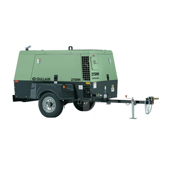
This model meets EPA sound maintenance. Compared to other compressors, Sullair’s level regulations of 76dbA at 7 meters (23 feet). Sullair air are unique in terms of reliability and durability. Compressor compressors have the following delivery capacities: internal components require no routine maintenance inspections. - Page 18 Moisture Separator Battery Shutoff Switch Optional Discharge Air Filters Figure 2-1: Sullair Rotary Screw Portable Air Compressor – Caterpillar Standard and Aftercooled Models Refer to the engine operator’s manual for a more The control system can easily be adjusted for pressures from 80 to 125 psig (5.6 to 8.6 bar) for standard machines,...
-
Page 19: Sullair Compressor Unit, Functional Description
When the temperature reaches 155°F (68°C), the provide continuous (pulse-free) compression to meet thermostat is fully open allowing all fluid entering the various demand loads. Sullair compressors require no thermal valve to flow to the cooler. routine maintenance or inspection of their internal parts or The cooler is a radiator type that works in concert with the systems. -
Page 20: Compressor Discharge System, Functional Description
Refer to Figure 2-4, Figure 2-5 or Figure 2-6. The purpose of the control system is to regulate the amount of air intake Refer to Figure 2-3. The Sullair compressor unit and match it to the demand (required output) on the discharges a compressed air/fluid mixture into the sump. - Page 21 DeScriPtioN STANDARD MODEL AFTERCOOLED MODEL SU_0000665 Engine Service Air Outlet Strainer Receiver Tank (Sump) Minimum Pressure/Check Valve Optional Discharge Air Filters Service Air Outlet Moisture Separator Receiver Tank (Sump) Aftercooler Separator Element Minimum Pressure Valve Fluid/Air Non-Aftercooled/Aftercooled Service Air Valve Figure 2-3: Compressor Discharge System –...
- Page 22 SectioN 2 SU_0000666 CAT T2 Air Pressure Gauge Optional Aftercooler Instrument Panel Aftercooled Machines ONLY Idle Warm-Up Valve Fluid Filter Inlet Valve Thermal Valve Air Filter Compressor Unit Regulator/Blowdown Valve Manifold Fluid Cooler Minimum Pressure Check Valve Pressure Relief Valve Fluid/Air Fuid Fill/Fluid Level Sight Glass Fluid...
- Page 23 Fluid Cooler Inlet Valve Strainer Fluid/Air Minimum Pressure/Check Valve Fluid Pressure Relief Valve Engine Speed Control Cylinder Figure 2-5: Control System with Piping and Instrumentation – 300HH and 375H Models 375 Caterpillar Standard and Aftercooled/Filtered Operator’s Manual and Parts List...
- Page 24 SectioN 2 High Warm-up Start Low Pressure High Pressure Standard Air Moisture Drain Aftercooled Air 02250169-746R00-1 Figure 2-6: Piping and Instrumentation Diagram 375 Caterpillar Standard and Aftercooled/Filtered Operator’s Manual and Parts List...
- Page 25 DeScriPtioN Filter, Air Compressor Discharge Temperature Switch Gauge, Filter Restriction (Optional) Inlet Valve Compressor Gauge, Temperature Switch, Temperature Valve, Relief Receiver, Air/Oil Glass, Sight Oil Level Indicator, Delta-P Valve, Minimum Pressure/Check Valve, Ball Cooler, Air Separator, Moisture Trap, Drain Orifice Valve, Blowdown N.C.
-
Page 26: Normal Operation - 80 To 100 Psig (5.6 To 6.9 Bar) Or 80 To 150 Psig (5.6 To 10.3 Bar) For H Machines Or 80 To 200 Psig (5.6 To 13.8 Bar) For Hh Machines
SectioN 2 pressure increases, the inlet valve piston will further close the inlet valve and the engine speed will decrease until it reaches its preset idle speed. When the demand on the compressor increases, the sump pressure falls below 110 psig (7.6 bar) or 165 psig (11.4 bar) for “H”... - Page 27 DeScriPtioN Figure 2-9: Instrument Panel Group (Optional Full Gauge Panel Shown) Compressor discharge temperature System air pressure Start stop switch Warm-up control High/low pressure selector Warning indicator Hourmeter Engine voltage Engine oil pressure Engine coolant temperature Cold weather starting. (Glow plugs) Engine RPM (optional) Fuel level (optional) fig_instrpnl_375h_cat_t2-r00...
-
Page 28: Wiring Diagram
SectioN 2 wiriNG DiaGram 375 Caterpillar Standard and Aftercooled/Filtered Operator’s Manual and Parts List... -
Page 29: Electrical System, Functional Description
DeScriPtioN electrical SYStem, comPreSSor SHutDowN 2.10 2.11 fuNctioNal DeScriPtioN & warNiNG SYStem, fuNctioNal DeScriPtioN The electrical system consists of the basic electrical elements required to operate the compressor and also has The Shutdown System and Annunciator Module (SSAM) a system feature that automatically shuts down the continuously monitors the status of the compressor. -
Page 30: Aftercooled And Filtered Air System, Functional Description
SectioN 2 aftercooleD aND filtereD from the first stage filter. the condensate should be 2.12 drained and stored in a suitable container. From the air SYStem, fuNctioNal first stage filter, the air enters the (optional) second stage DeScriPtioN filter. This filter removes smaller particles and any additional water. -
Page 31: Specifications
Section 3 SPecificatioNS SPecificatioNS – 300HH aND 375 caterPillar DimeNSioNS model Series length (i) width Height weight (wet) 300HH, and 375 156.2 3967.5 77.2 1960.9 74.0 1879.6 4420* 2004.9* 2-Wheel 300HH, and 375 98.8 2509.5 59.3 1506.2 63.6 1615.4 4175* 1893.8*... -
Page 32: Specifications - 375H And 425 Caterpillar
SectioN 3 eNGiNe: 300HH Type Diesel Diesel Make Caterpillar Caterpillar Model C4.4 C4.4 Displacement 268 cu/in (4.4L) 268 cu/in (4.4L) Cylinders Bore x Stroke 4.13 x 5.00 4.13 x 5.00 (105 mm x 127 mm) (105 mm x 127 mm) - Page 33 SPecificatioNS Electrical System 12 volt 12 volt Compressor Discharge Temp Shutdown 250°F (121°C) Shutdown 250°F (121°C) Service Valves (2) ¾" (2) ¾" Maximum Towing Speed 55 mph (88 kmph) 55 mph (88 kmph) Axle Rating 5000 lbs 5000 lbs (2268 kg) (2268 kg) Sound Level 76 dBA at 7 m...
-
Page 34: 3.3 Lubrication Guide - Compressor
0 to 100 (-18 to 38) MIL-L-2104E 10W 0 to 100 (-18 to 38) (i) Sullair part numbers for Sullair AWF are 250030-757 (5 gallons/18.9 liters) and 250030-758 (55 gallon drum/208 liters). aPPlicatioN GuiDe Sullair air compressors are supplied with Sullair AWF... -
Page 35: General
Compressor Discharge Temperature Switch Opens the electrical circuit to shut down the compressor While Sullair has built into this compressor a complete set when the discharge temperature reaches a specific value of controls and indicators that allow the operator to control (See Specifications on page 25 and on page 27). -
Page 36: Initial Startup/Shutdown Procedure
SectioN 4 Blowdown Valve Shutdown Vents sump pressure to the atmosphere at shutdown. Close the service valves and run the compressor for approximately five minutes to allow the compressor to cool down. Idle Warm-Up Control Place the pressure selector switch in the low position Keeps the compressor inlet valve closed for reduced (H and HH models). -
Page 37: Maintenance
Section 5 maiNteNaNce warNiNG Note the radiator and engine cooling Do Not remove caps. Plugs system must be drained and flushed and/or other components when every 1500 hours. replace the the compressor is running or solution coolant with a 50% ethylene pressurized. -
Page 38: Maintenance After Initial 50 Hours Of Operation
SectioN 5 maiNteNaNce after iNitial 50 Change the compressor fluid if it is not Sullair AWF: HourS of oPeratioN Run the compressor for five to ten minutes to warm the fluid After the initial 50 hours of operation, the following... -
Page 39: Part Replacement And Adjustment Procedures
maiNteNaNce 5.8 Part rePlacemeNt aND Air Filter Maintenance aDJuStmeNt ProceDureS Refer to Figure 5-2. Air filter maintenance should be performed as often as conditions require. If the filters are equipped with optional maintenance indicators, change the Compressor Fluid Change Procedure filters every time the indicators show a change is Run the compressor five to ten minutes to warm the necessary. -
Page 40: Element Inspection
Refer to Figure 5-4 and Figure 5-5. Before adjusting the compressor’s control system, the rated full-load pressure and the high/low rpm settings must be determined. This information is provided in Specifications on page 25 and on page 26 or can be obtained by contacting a Sullair representative. SU_0000670 Capscrew... - Page 41 maiNteNaNce Open the service valve to 100 psig (6.9 bar) (rated full load pressure) and recheck top engine speed and control response. Close the service valve and allow the compressor to cycle and re-check low engine speed (idle). Compressor Unit Air Pressure Gauge Warm-Up Control Valve High/Low Pressure Valve...
-
Page 42: Bearing Lubrication
SectioN 5 The following steps apply to “H” and “HH” compressors Bearing Lubrication equipped with dual pressure controls. Refer to Figure 5-6. Proper lubrication of the portable Start the compressor and allow the engine to warm up compressor’s bearing axle is critical to its proper function to its normal operating temperature with the service and reduction of wear on this part. -
Page 43: First And Second Stage Discharge Air Filter Maintenance - Aftercooled & Filtered Models
maiNteNaNce First and Second Stage Discharge Air Filter Maintenance – Aftercooled & Filtered Models General Refer to Figure 5-7. Familiarity with the filtration process and the unit’s monitoring system (consisting of a compete set of gauges) will enable the operator to locate and analyze malfunctions. -
Page 44: 5.9 Trouble Shooting
Performing a detailed visual inspection in all cases can malfunction is not covered in this Trouble Shooting chart, prevent additional damage or abnormal operation. contact your nearest Sullair representative or Sullair for technical assistance. eNGiNe DoeS Not craNk or craNkS but DoeS Not Start... - Page 45 maiNteNaNce eNGiNe DoeS Not craNk or craNkS but DoeS Not Start SYmPtom Probable cauSe remeDY Did not start compressor within the 30 After turning the ignition switch to the ON SSAM FLASH CODE:FOUR FLASHES seconds from turning the ignition switch to position, press the switch to the START the ON position position within 30 seconds...
- Page 46 SectioN 5 comPreSSor SHutS DowN SYmPtom Probable cauSe remeDY COMPRESSOR DOES NOT ACHIEVE Run/start switch not in run position For compressors with idle warm-up FULL DISCHARGE PRESSURE controls, switch toggle to RUN for full operation Air demand is excessive Check service lines for leaks or open valves Dirty air filter Check the filter and change the element if...
- Page 47 maiNteNaNce comPreSSor SHutS DowN SYmPtom Probable cauSe remeDY COMPRESSOR OVERHEATING Low receiver tank fluid level Fill receiver tank Loose or broken fan belt Tighten or replace belt Dirty fluid cooler core Clean core thoroughly Plugged compressor fluid filter Change element Faulty thermostat Change thermostat element Plugged fluid cooler tube (internal)
- Page 48 SectioN 5 tHiS PaGe iNteNtioNallY left blaNk 375 Caterpillar Standard and Aftercooled/Filtered Operator’s Manual and Parts List...
-
Page 49: Noise Control
The use of the compressor after such device or element of design has been removed or rendered inoperative by any person. Sullair Corporation warrants to the ultimate purchaser and each subsequent purchaser that this air compressor was designed, built and equipped to conform at the time of sale Among those acts included in the prohibition against to the first retail purchaser, with all applicable U.S. -
Page 50: Noise Emission Maintenance And Maintenance Record Log
SectioN 6 NoiSe emiSSioNS maiNteNaNce aND maiNteNaNce recorD loG The following instructions and maintenance record log book, for the proper maintenance, use and repair of this compressor, is intended to prevent noise emission degradation. Noise Emission Maintenance and Maintenance Record Log 1. - Page 51 NoiSe coNtrol 3. aNNual eNGiNe VibratioN mouNt iNSPectioN At least annually inspect engine vibration mounts for security of attachment and to make sure the resilient parts are intact. DO NOT operate compressor with defective engine mounting system. Remove and replace defective parts by ordering with part numbers indicated in Parts List.
- Page 52 SectioN 6 6. aNNual iNSPectioNS for ProPer oPeratioN of all SYStemS. In addition to other instructions in the Operator’s Manual, at least annually, operate compressor and inspect to make sure all systems are operating properly and that engine runs at rated speed and pressure. DO NOT operate malfunctioning or improperly adjusted compressor.
-
Page 53: Procedure For Ordering Parts
Serial Number Plate on the front of the compressor (see Figure 7-1). Parts should be ordered from the nearest Sullair representative or the representative from whom the compressor was purchased. If parts cannot be obtained... - Page 54 SectioN 7 375 Caterpillar Standard and Aftercooled/Filtered Operator’s Manual and Parts List...
-
Page 55: Recommended Spare Parts List
02250094-294 250019-444 repair kit for shaft seal 602541-002 repair coupling assemblies (375) 250031-586 repair coupling assemblies (300HH, 375H, & 425 ) 250024-470 Sullair AWF (5 gallons/18.9 liters) 250030-757 Sullair AWF (55 gallon drum/208 liters) 250030-758... -
Page 56: Engine, Compressor And Parts
SectioN 7 eNGiNe, comPreSSor aND PartS 02250170-256-r00 375 Caterpillar Standard and Aftercooled/Filtered Operator’s Manual and Parts List... - Page 57 illuStratioNS aND PartS liSt 7.3 eNGiNe, comPreSSor aND PartS (CONTINuED) Description Part Number Note Quantity valve, drain eng oil 19mm x 1.50 02250051-231 key,shaft step 375h 02250053-263 elbow,check valve 1/4t x 1/8p 02250058-275 spacer, brake lever 250p 02250064-594 washer, rtnr ctl cyl spring 5/16" 02250078-842 conn, female pipe 1/8-27 npt 02250097-138...
- Page 58 SectioN 7 7.3 eNGiNe, comPreSSor aND PartS (CONTINuED) 02250170-256-r00 375 Caterpillar Standard and Aftercooled/Filtered Operator’s Manual and Parts List...
- Page 59 illuStratioNS aND PartS liSt 7.3 eNGiNe, comPreSSor aND PartS (CONTINuED) Description Part Number Note Quantity nut,hex locking 1/4-20 825504-145 nut,hex locking 5/8-11 825510-329 capscrew,hex 8.8 m6 x 16mm 828006-016 capscrew,hex 8.8 m8 x 100mm 828008-100 capscrew,hex 8.8 m10 x 35mm 828010-035 capscrew,hex 8.8 m12 x 25mm 828012-025...
-
Page 60: Radiator & Compressor Fluid Cooling System
SectioN 7 raDiator & comPreSSor fluiD cooliNG SYStem 02250166-333R02-CAT 375 Caterpillar Standard and Aftercooled/Filtered Operator’s Manual and Parts List... - Page 61 illuStratioNS aND PartS liSt 7.4 raDiator & comPreSSor fluiD cooliNG SYStem (CONTINuED) Description Part Number Note Quantity bucket, radiator fluid recovery 02250083-466 hose, mp 1" x 48" lg 02250088-283 elb, 90 sae x orfs 1.25" x 1.00" 02250093-804 filter, fluid 1 5/8 sae str thrd co 02250096-783 housing, thermo vlv leak free 375 02250113-796...
- Page 62 SectioN 7 7.4 raDiator & comPreSSor fluiD cooliNG SYStem (CONTINuED) 02250166-333R02-CAT 375 Caterpillar Standard and Aftercooled/Filtered Operator’s Manual and Parts List...
- Page 63 illuStratioNS aND PartS liSt 7.4 raDiator & comPreSSor fluiD cooliNG SYStem (CONTINuED) Description Part Number Note Quantity washer, spr lock reg pltd 5/16 837805-078 washer, pl-b reg pltd 5/16 838205-071 hose, fuel line 5/16 (ft) 842315-031 nut, retainer 5/16-18 .092 861405-092 reducer, str thrd viton 1 1/4 x 1 870020-016...
-
Page 64: Air Inlet System & Exhaust System
SectioN 7 air iNlet SYStem & exHauSt SYStem 02250166-339R00 375 Caterpillar Standard and Aftercooled/Filtered Operator’s Manual and Parts List... - Page 65 illuStratioNS aND PartS liSt 7.5 air iNlet SYStem & exHauSt SYStem (CONTINuED) Description Part Number Note Quantity elbow, 90m 5/16"tube x 1/8"npt 02250109-423 gasket, exht ca3054na 185q 02250110-425 tube,exhaust 375-425 cat 02250115-010 muffler, exhaust 300h-425 ft mtg 02250115-201 hose, air inlet eng (part 1) 02250140-336 tube, aluminum 3.5"od x 4"lg 16ga 02250140-363...
-
Page 66: Control Parts & Discharge Parts - 375 And 425
SectioN 7 coNtrol PartS & DiScHarGe PartS - 375 aND 425 02250170-257-r02 375 Caterpillar Standard and Aftercooled/Filtered Operator’s Manual and Parts List... - Page 67 375-600 t3 02250164-704 (III) support, reg/bd assy 375-600 t3 02250166-243 sub assembly,reg/bd assy 375 cat t2 exp 02250169-280 (IV) tank, air/oil sep 300hh-600 02250170-513 plug,o-ring boss sae 1 1/4 040029 strainer, v-type 300psix1/4 241771 tube,steel 5/16"od oil siphon 250009-253...
- Page 68 SectioN 7 7.6 coNtrol PartS & DiScHarGe PartS - 375 aND 425 (CONTINuED) 02250170-257-r02 375 Caterpillar Standard and Aftercooled/Filtered Operator’s Manual and Parts List...
- Page 69 illuStratioNS aND PartS liSt 7.6 coNtrol PartS & DiScHarGe PartS - 375 aND 425 (CONTINuED) Description Part Number Note Quantity washer, pl-b reg pltd 3/8 838206-071 elbow, 37fl 90m 1 1/2 x 1 1/2 860224-150 nipple,pipe-xs plt 1 x cl 866416-000 nipple,pipe-xs plt 1 1/2 x cl 866424-000...
-
Page 70: Control Parts & Discharge Parts - 300Hh And 375H
SectioN 7 coNtrol PartS & DiScHarGe PartS - 300HH aND 375H 02250170-258-r02 375 Caterpillar Standard and Aftercooled/Filtered Operator’s Manual and Parts List... - Page 71 PartS liSt 7.7 coNtrol PartS & DiScHarGe PartS - 300HH aND 375H (CONTINuED) Description Part Number Note Quantity valve, relief 3/4" x 1 1/4"fnpt 02250047-678 insert, nylon tubing 1/4"od 02250052-841 tube,nyl .25 od x 040w wht(ft) 02250054-860 tube, nylon .25"od x .04w black (ft) 02250054-861 tube,5/16 od x .040 wall...
- Page 72 SectioN 7 7.7 coNtrol PartS & DiScHarGe PartS - 300HH aND 375H (CONTINuED) 02250170-258-r02 375 Caterpillar Standard and Aftercooled/Filtered Operator’s Manual and Parts List...
- Page 73 PartS liSt 7.7 coNtrol PartS & DiScHarGe PartS - 300HH aND 375H (CONTINuED) Description Part Number Note Quantity washer, spr lock 1/2 837508-125 washer, pl-b reg pltd 3/8 838206-071 elbow, 37fl 90m 1 1/2 x 1 1/2 860224-150...
-
Page 74: Regulator/Blowdown Valve - 375 And 425
SectioN 7 7.8 reGulator/blowDowN ValVe - 375 aND 425 02250169-281-r01 375 Caterpillar Standard and Aftercooled/Filtered Operator’s Manual and Parts List... - Page 75 illuStratioNS aND PartS liSt 7.8 reGulator/blowDowN ValVe - 375 aND 425 (CONTINuED) Description Part Number Note Quantity connector,5/16" tube x 1/4" npt 02250081-219 tee,m run 3/8" tube x 1/4" npt 02250099-615 connector,3/8" tube x 1/2" npt 02250129-957 manifold, regulator blowdown 185 02250146-046 connector,3/8"...
-
Page 76: Regulator/Blowdown Valve - 300Hh And 375H
SectioN 7 reGulator/blowDowN ValVe - 300HH aND 375H 02250168-640-r01 375 Caterpillar Standard and Aftercooled/Filtered Operator’s Manual and Parts List... - Page 77 PartS liSt 7.9 reGulator/blowDowN ValVe - 300HH aND 375H (CONTINuED) Description Part Number Note Quantity connector,5/16"tube x 1/4"npt 02250081-219 tee,m run 3/8"tube x 1/4"npt 02250099-615 elbow, 90 3/8"tube x 1/4"npt m 02250099-626 connector,3/8 tube x 1/4npt 02250148-188 manifold, press reg/bd 150psi 185h...
-
Page 78: 7.10 Control Parts Orifice - 300Hh And 375H
SectioN 7 7.10 coNtrol PartS orifice - 300HH aND 375H 02250169-279-r00 375 Caterpillar Standard and Aftercooled/Filtered Operator’s Manual and Parts List... - Page 79 PartS liSt 7.10 coNtrol PartS orifice - 300HH aND 375H (CONTINuED) Description Part Number Note Quantity orifice,ctl .078 1/8 fnpt x 1/8 mnpt 02250069-264 tee,m run 3/8"tube x 1/4"npt 02250099-615 silencer, air ejection 1/8"npt-male thread 248755 tee, pipe 150# plt 1/4...
-
Page 80: 7.11 Service Valves
SectioN 7 7.11 SerVice ValVeS 02250118-602R02 375 Caterpillar Standard and Aftercooled/Filtered Operator’s Manual and Parts List... - Page 81 illuStratioNS aND PartS liSt 7.11 SerVice ValVeS (CONTINuED) Description Part Number Note Quantity valve, double ball 3/4" x 1" 250019-916 coupling, 3/4" female npt 040383 375 Caterpillar Standard and Aftercooled/Filtered Operator’s Manual and Parts List...
-
Page 82: Optional Aftercooler/Filter And Parts
SectioN 7 oPtioNal aftercooler/filter aND PartS 7.12 02250166-353R02 375 Caterpillar Standard and Aftercooled/Filtered Operator’s Manual and Parts List... - Page 83 illuStratioNS aND PartS liSt 7.12 oPtioNal aftercooler/filter aND PartS (CONTINuED) Description Part Number Note Quantity valve, blowdown 1/4 npt hi prs 02250049-634 hose, medium pressure 250psi 1.5" x 38" fjic 02250051-446 tube, nyl .25 od x .040w blk (ft) 02250054-861 tube, nylon .375"...
- Page 84 SectioN 7 7.12 oPtioNal aftercooler/filter aND PartS (CONTINuED) 02250166-353R02 375 Caterpillar Standard and Aftercooled/Filtered Operator’s Manual and Parts List...
- Page 85 illuStratioNS aND PartS liSt 7.12 oPtioNal aftercooler/filter aND PartS (CONTINuED) Description Part Number Note Quantity bushing, red pltd 1/4 x 1/8 867100-005 bushing, red pltd 1 1/2 x 1/4 867106-010 coupling, pipe 1/4 300# plt 867430-010 tee, pipe pltd 1 1/2 868430-060 elbow, pipe 45 deg 300# plt 1 1/2"...
-
Page 86: Electrical Parts
SectioN 7 electrical PartS 7.13 02250170-262-r00 375 Caterpillar Standard and Aftercooled/Filtered Operator’s Manual and Parts List... - Page 87 illuStratioNS aND PartS liSt 7.13 electrical PartS (CONTINuED) Description Part Number Note Quantity channel, extruded rubber “u” .25"w (ft) 02250086-448 washer, external serrated m10 02250092-169 cable, ground 4-gauge strap 02250101-258 battery, grp 31 hi cap taper post 02250114-276 lamp,license plate std 02250119-658 harness, 6-wire lites 375 02250119-673...
-
Page 88: Instrument Panel & Parts
SectioN 7 iNStrumeNt PaNel & PartS 7.14 02250170-259-r01 375 Caterpillar Standard and Aftercooled/Filtered Operator’s Manual and Parts List... - Page 89 02250154-331 PANEL, INSTRUMENT 375H CA STD T2 ExP 02250154-332 PANEL, INSTRUMENT 375 CA FULL T2 ExP 02250154-333 PANEL, INSTRUMENT 375H CA FULL T2 ExP * P/N 02250154-331 for 300HH and 375H (I) For color variations consult factory. 375 Caterpillar Standard and Aftercooled/Filtered Operator’s Manual and Parts List...
- Page 90 SectioN 7 7.14 iNStrumeNt PaNel & PartS (CONTINuED) 02250154-333-r02 375 Caterpillar Standard and Aftercooled/Filtered Operator’s Manual and Parts List...
- Page 91 838200-045 bushing,red pltd 1/4 x 1/8 867100-005 300HH and 375HH models only (II) Use P/N 02250144-353 for replacement of glow plug relay, P/N 02250153-875 for replacement of starter relay and P/N 02250155-383 for replacement of shutdown relay. 375 Caterpillar Standard and Aftercooled/Filtered Operator’s Manual and Parts List...
-
Page 92: Fuel Tank & Connections
SectioN 7 fuel taNk & coNNectioNS 7.15 02250170-261-r00 375 Caterpillar Standard and Aftercooled/Filtered Operator’s Manual and Parts List... - Page 93 illuStratioNS aND PartS liSt 7.15 fuel taNk & coNNectioNS (CONTINuED) Description Part Number Note Quantity adapter,1/2str oring x 1/4 fnpt 02250075-714 tube,fuel return 1/4" jd 185q 02250102-573 connector, tube oil return 1/4 x 1/4 02250108-700 filter, ass’y fuel/water sep 02250118-494 plug,fuel/water sep 1/2-20 unf 02250118-524 connector, tube oil return 5/16x1/4...
-
Page 94: Frame, Axle & Parts And Axle Assembly
SectioN 7 frame, axle & PartS aND axle aSSemblY 7.16 02250166-334R02 375 Caterpillar Standard and Aftercooled/Filtered Operator’s Manual and Parts List... - Page 95 illuStratioNS aND PartS liSt 7.16 frame, axle & PartS aND axle aSSemblY (CONTINuED) Description Part Number Note Quantity reflector, red 3" truck-lite 02250052-701 reflector, yellow 3" truck-lite 02250052-702 nut, shackle (dexter 6-7) 02250058-263 bolt, shackle (dexter 7-17) 02250058-267 washer, flat hardened 1/2" 02250064-266 tire, assembly h78-15 st d 02250100-518...
- Page 96 SectioN 7 7.16 frame, axle & PartS aND axle aSSemblY (CONTINuED) 02250166-334R02 375 Caterpillar Standard and Aftercooled/Filtered Operator’s Manual and Parts List...
- Page 97 illuStratioNS aND PartS liSt 7.16 frame, axle & PartS aND axle aSSemblY (CONTINuED) Description Part Number Note Quantity washer, pl-b reg pltd 1/2 838208-112 washer, pl-b reg pltd 5/8 838210-112 nut, retainer 5/16-18 .092 861405-092 capscrew, hex gr5 1/2-13 x 1 1/4 plt 875608-125 screw, flt phillips 8-32 x 3/4"...
-
Page 98: Axle Assembly
SectioN 7 axle aSSemblY 7.17 02250116-323R01 375 Caterpillar Standard and Aftercooled/Filtered Operator’s Manual and Parts List... - Page 99 02250154-331 PANEL, INSTRUMENT 375H CA STD T2 ExP 02250154-332 PANEL, INSTRUMENT 375 CA FULL T2 ExP 02250154-333 PANEL, INSTRUMENT 375H CA FULL T2 ExP (I) For color variations consult factory. * P/N 02250154-331 for 300HH and 375H 375 Caterpillar Standard and Aftercooled/Filtered Operator’s Manual and Parts List...
-
Page 100: Canopy, Acoustical Panels & Parts
SectioN 7 caNoPY, acouStical PaNelS & PartS 7.18 02250166-351R01 375 Caterpillar Standard and Aftercooled/Filtered Operator’s Manual and Parts List... - Page 101 illuStratioNS aND PartS liSt 7.18 caNoPY, acouStical PaNelS & PartS (CONTINuED) Description Part Number Note Quantity catch, pivot slam pad lck blk - 02250107-837 insulation, clr baff fill 185h 02250147-126 panel, can frt rh 375 t3 02250164-802 panel, can frt lh 375 t3 02250164-807 panel, can rear rh 375t3 02250164-812...
-
Page 102: Decals
SectioN 7 DecalS 7.19 02250140-925 SU_0000681 CAT T2 375 Caterpillar Standard and Aftercooled/Filtered Operator’s Manual and Parts List... - Page 103 illuStratioNS aND PartS liSt 7.19 DecalS (CONTINuED) Description Part Number Note Quantity DECAL, OPER. INTRUCTIONS - CAT 02250133-511 decal, "need an air tool" sml 02250140-925 decal, drwbr instl 185q pe std 02250142-050 decal, diesel fuel 040248 (I) OSHA guidelines are superseded by any federal, state or local regulations whenever applicable. 375 Caterpillar Standard and Aftercooled/Filtered Operator’s Manual and Parts List...
- Page 104 SectioN 7 7.19 DecalS (CONTINuED) SU_0000682 375 Caterpillar Standard and Aftercooled/Filtered Operator’s Manual and Parts List...
- Page 105 illuStratioNS aND PartS liSt 7.19 DecalS (CONTINuED) Description Part Number Note Quantity decal, warning tongue heavy 100-375 02250077-929 decal, warning side door T-latch 02250136-670 decal, lead warning proposition 65 02250118-638 sign, warning hot surfaces 407408 OSHA guidelines are superseded by any Federal, State or Local regulations whenever applicable. 375 Caterpillar Standard and Aftercooled/Filtered Operator’s Manual and Parts List...
- Page 106 SectioN 7 7.19 DecalS (CONTINuED) SU_0000683 375 Caterpillar Standard and Aftercooled/Filtered Operator’s Manual and Parts List...
- Page 107 illuStratioNS aND PartS liSt 7.19 DecalS (CONTINuED) Description Part Number Note Quantity decal, caution do not overfill 02250142-530 decal, noise emission control 049463 decal, 5 year warranty 02250097-455 decal, rated 2200 idle 1600 rpm 02250146-383 reflector, red 040103 reflector, amber 250034-319 375 Caterpillar Standard and Aftercooled/Filtered Operator’s Manual and Parts List...
- Page 108 SectioN 7 7.19 DecalS (CONTINuED) SU_0000684 375 Caterpillar Standard and Aftercooled/Filtered Operator’s Manual and Parts List...
- Page 109 PartS liSt 7.19 DecalS (CONTINuED) Description Part Number Note Quantity decal, “300HH Sullair” frnt blk 02250139-154 decal, “375 Sullair” frnt blk 02250117-349 decal, “375H Sullair” frnt blk 02250117-352 decal, “425 Sullair” frnt blk 02250118-606 decal, “300HH” 3" tall blk 02250165-929 decal, “375”...
- Page 110 SectioN 7 7.19 DecalS (CONTINuED) 02250168-596R00 375 Caterpillar Standard and Aftercooled/Filtered Operator’s Manual and Parts List...
- Page 111 PartS liSt 7.19 DecalS (CONTINuED) Description Part Number Note Quantity decal,maint 300hh-425 ca t2 ex 02250168-596 375 Caterpillar Standard and Aftercooled/Filtered Operator’s Manual and Parts List...
- Page 112 SectioN 7 7.19 DecalS (CONTINuED) 02250144-396R04 02250075-505-r00 02250119-385-r01 375 Caterpillar Standard and Aftercooled/Filtered Operator’s Manual and Parts List...
- Page 113 illuStratioNS aND PartS liSt 7.19 DecalS (CONTINuED) Description Part Number Note Quantity decal,wd 375 cat tier ii 02250144-396 decal, aftercooled/filtered air 02250075-506 decal, aftercooler by-pass valve 02250119-385 375 Caterpillar Standard and Aftercooled/Filtered Operator’s Manual and Parts List...
-
Page 114: Decal Locations
SectioN 7 Decal locatioNS 7.20 375 Caterpillar Standard and Aftercooled/Filtered Operator’s Manual and Parts List... - Page 115 65 02250118-638 decal, operator procedure start stop 375 cat 02250133-511 decal, warning side door t-latch 02250136-670 decal, “300HH Sullair” frt blk 02250139-154 decal, “need an air tool?” sml 02250140-925 decal, drwbr instl 185q pe std 02250142-050...
- Page 116 SectioN 7 7.20 Decal locatioNS 375 Caterpillar Standard and Aftercooled/Filtered Operator’s Manual and Parts List...
- Page 117 Quantity decal, water drain 040345 decal, warning cluster breath 250028-258 sign, warning compr oil fill cap 049685 decal, sullair awf instruction 250032-902 sign, warning sever fan port 049965 sign, warning sever belt drive 049964 sign, caution towing 55 mph 250005-578...
- Page 118 SectioN 7 tHiS PaGe iNteNtioNallY left blaNk 375 Caterpillar Standard and Aftercooled/Filtered Operator’s Manual and Parts List...
- Page 119 illuStratioNS aND PartS liSt warNiNG califorNia Proposition 65 warning Diesel engine exhaust and some of its constituents are known to the State of california to cause cancer, birth defects and other repoductive harm. battery posts, terminals and related accessories contain lead and other compounds known to the State of california to cause cancer and birth defects and...
- Page 120 orldWide aleS and ervice Printed in the u.S.a Specifications subject to change...
Need help?
Do you have a question about the 300HH and is the answer not in the manual?
Questions and answers