Table of Contents
Advertisement
proform.com
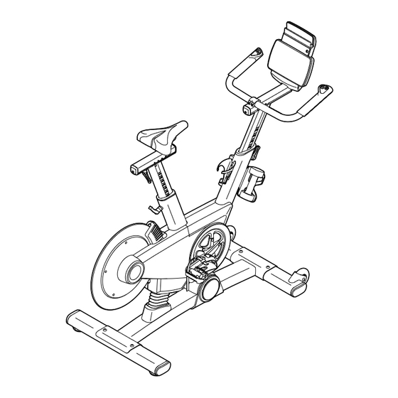
Model No. PFEX09916.1
Serial No.
USER'S MANUAL
Write the serial number in the space
above for reference.
Serial Number
Decal
ACTIVATE YOUR
WARRANTY
To register your product and
activate your warranty today,
go to my.proform.com.
CUSTOMER CARE
For service at any time, go to
proformservice.com.
Or call 1-877-660-1168
Mon.–Fri. 6 a.m.–6 p.m. MT
Sat. 8 a.m.–12 p.m. MT
Please do not contact the store.
CAUTION
Read all precautions and
instructions in this manual before
using this equipment. Keep this
manual for future reference.
Advertisement
Table of Contents

Related Manuals for Pro-Form LE TOUR DE FRANCE PFEX09916.1


Summary of Contents for Pro-Form LE TOUR DE FRANCE PFEX09916.1
- Page 1 proform.com Model No. PFEX09916.1 Serial No. USER’S MANUAL Write the serial number in the space above for reference. Serial Number Decal ACTIVATE YOUR WARRANTY To register your product and activate your warranty today, go to my.proform.com. CUSTOMER CARE For service at any time, go to proformservice.com.
-
Page 2: Table Of Contents
TABLE OF CONTENTS WARNING DECAL PLACEMENT ............. . .2 IMPORTANT PRECAUTIONS . -
Page 3: Important Precautions
IMPORTANT PRECAUTIONS WARNING: To reduce the risk of burns, fire, electric shock, or injury to persons, read all important precautions and instructions in this manual and all warnings on your training bike before using your training bike. ICON assumes no responsibility for personal injury or property damage sustained by or through the use of this product. - Page 4 STANDARD SERVICE PLANS...
-
Page 5: Before You Begin
BEFORE YOU BEGIN Congratulations for selecting the revolutionary reading this manual, please see the front cover of this PROFORM LE TOUR DE FRANCE training bike. manual. To help us assist you, note the product model ® ® The LE TOUR DE FRANCE training bike is unlike any number and serial number before contacting us. -
Page 6: Part Identification Chart
PART IDENTIFICATION CHART Use the drawings below to identify the small parts needed for assembly. The number in parentheses below each drawing is the key number of the part, from the PART LIST near the end of this manual. The number following the key number is the quantity needed for assembly. -
Page 7: Assembly
ASSEMBLY • To hire an authorized service technician to • To identify small parts, see page 6. assemble the training bike, call 1-800-445-2480. • In addition to the included tool(s), assembly • Assembly requires two persons. requires the following tools: one Phillips screwdriver •... -
Page 8: Indicated Adjustment Handle (47), And Insert
3. If there are shipping screws in the Rear Stabilizer (23), remove and discard them. Attach the Rear Stabilizer (23) to the Base (1) with two M10 x 58mm Screws (74). 4. Using a plastic bag to keep your fingers clean, apply some of the included grease to the sides Grease of the channel on the top of the Saddle Post (3). -
Page 9: Indicated Adjustment Handle (47), And Insert
5. Note: You can attach your own saddle to the Saddle Carriage (4) if desired. Loosen the attachment hardware (not shown) beneath the Saddle (5), and remove the Saddle. Then, attach your own saddle and retighten the attachment hardware. Orient the Saddle Carriage (4) as shown. Loosen the Adjustment Handle (47), and slide the Saddle Carriage (4) into the Saddle Post (3). - Page 10 7. Have a second person hold the Handlebar (7) near the Handlebar Carriage (105). Locate the wire tie (D) in the right side of the Handlebar (7). Tie the indicated end of the wire tie to the Right Control Wire (81), which is marked with a tag.
- Page 11 10. Have a second person hold the Console (9) near the Console Bracket (124). Connect the console wires to the Handlebar Post Wire (68) and the Control Wires (70, 81); make sure to connect the console wire that has an “L”...
- Page 12 13. Attach the Water Bottle Holder (129) to the Frame (2) with two M4 x 10mm Screws (116). 14. Attach the Tray (8) to the Frame (2) with two M4 x 10mm Screws (116). Then, set the two Hand Weights (128) in the Tray (8).
-
Page 13: How To Use The Training Bike
HOW TO USE THE TRAINING BIKE HOW TO PLUG IN THE POWER CORD A temporary adapter may 2-pole Receptacle This product must be grounded. If it should mal- be used to function or break down, grounding provides a path of connect the Adapter least resistance for electric current to reduce the risk... -
Page 14: Part List
FEATURES OF THE TRAINING BIKE HOW TO ADJUST THE GEOMETRY OF THE TRAINING BIKE Measuring Watts The training bike can be adjusted to promote correct Each training bike is individually calibrated to measure form and to ensure proper training of the muscles. your power output and allow you to monitor your watts Note: Make adjustments in small increments, and and RPMs directly on the console. -
Page 15: Handle
How to Adjust the Saddle Post How to Adjust the Handlebar Post For effective train- To adjust the height ing, the saddle of the handlebar should be at the post (H), loosen proper height. As the adjustment you pedal, there handle (I), move should be a slight the handlebar post... - Page 16 HOW TO LEVEL THE TRAINING BIKE HOW TO USE THE HAND WEIGHTS If the training bike To add strength- rocks slightly on training exercise to your floor during your workouts, use use, turn one or the hand weights both of the leveling (O).
- Page 17 CONSOLE DIAGRAM FEATURES OF THE CONSOLE The console also offers a selection of onboard workouts. Each workout automatically changes the The advanced console offers an array of features incline of the training bike and allows you to change designed to make your workouts more effective and the resistance to maintain your pedaling cadence.
- Page 18 HOW TO TURN ON THE POWER HOW TO USE THE MANUAL MODE IMPORTANT: If the training bike has been exposed 1. Begin pedaling or press any button on the to cold temperatures, allow it to warm to room tem- console to turn on the console. perature before you turn on the power.
- Page 19 5. Change the resistance of the training bike as 7. Follow your progress with the power ring, and desired. set a power output target, if desired. As you pedal, you can The power ring change the resistance will provide a Solid Bar to make pedaling easier visual representa-...
- Page 20 IMPORTANT: The power output target is Scan mode—The console also has a scan mode intended only to provide motivation. Make sure that will display workout information in a repeating to pedal at a speed, a resistance level, and an cycle. To select the scan mode, press the Display incline level that is comfortable for you.
- Page 21 HOW TO USE AN ONBOARD WORKOUT The power ring will show a flashing indicator that represents the power output target for the segment. 1. Begin pedaling or press any button on the The solid bar represents your actual power output console to turn on the console.
- Page 22 HOW TO USE THE SOUND SYSTEM THE OPTIONAL CHEST HEART RATE MONITOR To play music or audio books through the console Whether your sound system while you exercise, plug a 3.5 mm male goal is to to 3.5 mm male audio cable (not included) into the burn fat or to jack on the console and into a jack on your personal strengthen your...
- Page 23 HOW TO CONNECT YOUR TABLET TO THE 5. Disconnect your tablet from the console if CONSOLE desired. The console supports BLUETOOTH connections to To disconnect your tablet from the console, first tablets via the iFit Bluetooth Tablet app and to compat- select the disconnect option in the iFit Bluetooth ible heart rate monitors.
- Page 24 THE SETTINGS MODE To calibrate the incline system, press the Incline increase or decrease button. The training bike 1. Select the settings mode. will automatically move forward and backward to the maximum incline and decline levels, and then To select the settings mode, press and hold down return to the starting position.
-
Page 25: Fcc Information
FCC INFORMATION This equipment has been tested and found to comply with the limits for a Class B digital device, pursuant to part 15 of the FCC Rules. These limits are designed to provide reasonable protection against harmful interference in a residential installation. This equipment generates, uses, and can radiate radio frequency energy and, if not installed and used in accordance with the instructions, may cause harmful interference to radio communications. -
Page 26: Maintenance And Troubleshooting
MAINTENANCE AND TROUBLESHOOTING HOW TO MAINTAIN THE TRAINING BIKE HOW TO ADJUST THE DRIVE BELT Regular maintenance is important for optimal If the pedals slip while you are pedaling, the drive belt performance and to reduce wear. Inspect and properly may need to be adjusted. -
Page 27: Exercise Guidelines
EXERCISE GUIDELINES Aerobic Exercise—If your goal is to strengthen your WARNING: cardiovascular system, you must perform aerobic Before beginning this exercise, which is activity that requires large amounts or any exercise program, consult your physi- of oxygen for prolonged periods of time. For aerobic cian. - Page 28 SUGGESTED STRETCHES The correct form for several basic stretches is shown at the right. Move slowly as you stretch; never bounce. 1. Toe Touch Stretch Stand with your knees bent slightly and slowly bend forward from your hips. Allow your back and shoulders to relax as you reach down toward your toes as far as possible.
-
Page 29: Part List
PART LIST Model No. PFEX09916.1 R0517A Key No. Qty. Description Key No. Qty. Description Base Board Bracket Frame Standoff Saddle Post Crank/Torque Pulley Saddle Carriage M4 Washer Saddle Magnet Handlebar Post Crank Screw Handlebar Bearing Tray Push Nut Console Frame Bushing Upper Shield Pivot Axle Left Shield... - Page 30 Key No. Qty. Description Key No. Qty. Description Reed Switch/Wire Swivel Tube Crank Hub Swivel Bushing Crank Spacer Swivel Tube Cap M8 Locknut Handlebar Carriage Cover Handlebar Carriage Console Bracket M8 x 20mm Screw Swivel Tube Bushing Right Extension Wire M8 x 35mm Bolt Left Extension Wire M8 x 52mm Bolt...
-
Page 31: Exploded Drawing
EXPLODED DRAWING Model No. PFEX09916.1 R0517A... -
Page 32: Ordering Replacement Parts
ORDERING REPLACEMENT PARTS To order replacement parts, please see the front cover of this manual. To help us assist you, be prepared to provide the following information when contacting us: • the model number and serial number of the product (see the front cover of this manual) •...
Need help?
Do you have a question about the LE TOUR DE FRANCE PFEX09916.1 and is the answer not in the manual?
Questions and answers