Advertisement
Quick Links
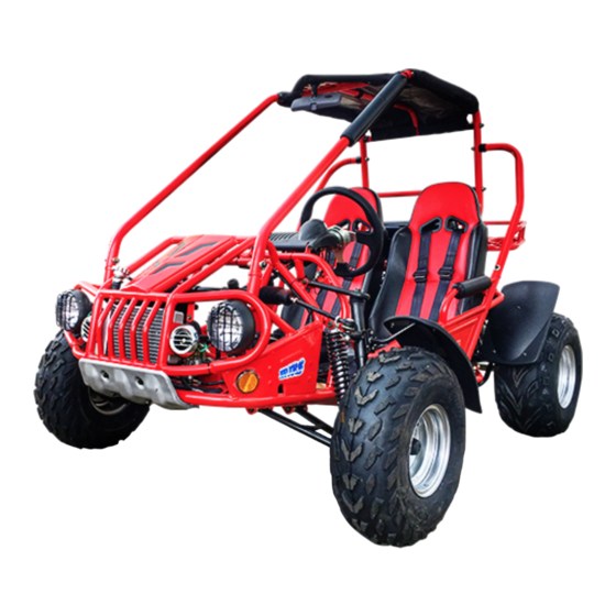
1
Move carton to a clean location with 3
or more feet of room around the unit.
2
Remove strapping and outer container.
3
Unpack parts and place near where
they are to be installed.
4
Lay out ALL hardware on a clean sur-
face and count.
5
Remove battery box from kart. Read all
precautions, filling instructions and
safety instructions. Make sure to wear safety
glasses and protective gloves.
6
Place the battery in a sink.
Advertisement

Related Manuals for TrailMaster 150


Summary of Contents for TrailMaster 150
- Page 1 Move carton to a clean location with 3 Lay out ALL hardware on a clean sur- or more feet of room around the unit. face and count. Remove strapping and outer container. Remove battery box from kart. Read all precautions, filling instructions and safety instructions.
- Page 2 Remove the battery cell seal. Place the battery acid container on top of the battery. Be sure to properly align the container with the battery cells. Carefully open the package containing Gently press the battery acid con- the battery acid and hardware. Set the tainer into the battery cells.
- Page 3 Allow the battery acid to fill the bat- Remove the hose from the frame be- tery while putting the go kart togeth- hind the driver’s seat. This fuel hose er or at least for 30 minutes. This will also al- will connect to the fuel petcock on the fuel low the battery to absorb the acid and vent tank later.
- Page 4 Insert the bolt with washer through Locate the vacuum hose that is al- the hole in the frame and turn the bolt ready connected to the fuel valve. to tighten the threads (clockwise rotation) into the rack. Do this procedure on both the left and right sides.
- Page 5 Locate fuel hose with the fuel filter Start all four bolts into the threads by and spring that is already attached to hand. Make sure that the steel bush- the carburetor. ing is inserted into each rubber bushing. Push the hose onto the top fitting of This is the rear support for the rear the fuel valve and slide the clamp to rack.
- Page 6 It is time to install the main bars on Insert the bolt, washers and nuts the cage. This step require 4 bolts, 4 through the bars at the front left side nuts and 8 cupped washers. and front right side. Nut should be to the in- side.
- Page 7 Four (4) 8mm bolts and washers will Install the bolt with washer in the top be used for the top weldment. of the bar first. Two (2) long bolts, nuts and four (4) Make sure the threads start into the washers along with two (2) long bolts bar.
- Page 8 Place the rear cross bar into place Use the remaining four (4) long 8mm and align holes. bolts and washers to install the top weldment. Start 8mm bolts with washers. Plastic end caps may need to be ro- tated with pliers to fit properly NOTE: DO NOT TIGHTEN HARDWARE YET.
- Page 9 Tighten ALL of the hardware previ- Align the shock. ously installed into the cage at this time with a 10mm wrench and a 12mm wrench. It is time to install the lower shock Insert the bolt and nut. bolts at the rear of the go-kart. Re- move the bolt and nut from the frame at the shock mount.
- Page 10 At this time, the go-kart must be lift- Steps 58 & 59 are not necessary, ed approximately 12” from the crate. however, we recommend using a You may need an assistant or two. Place a quality lubricant with straw. sturdy support under the kart frame i.e. jack- stands.
- Page 11 Place bolt through rear swing arm Install large washer and castle nut on located just in front of rear shock. axle. Start bolt into fender bracket by Tighten nut making sure to align with hand. Then, tighten firmly with a holes in axle.
- Page 12 Locate front passenger side spindle. Install stud in hole. Make sure rubber boot and square washer are installed. Align square stud with hole in A-arm. Make sure stud square is seated. Align square stud with lower A-arm. Install washer and castle nut.
- Page 13 Tighten nut. Align with hole in spin- Check castle nut for tightness. dle stud. Install cotter pin in lower spindle nut. Install cotter pin in upper spindle Bend and clip excess. nuts. Bend and clip excess. Remove cotter pin from top of spin- Remove cotter pin from ball joint.
- Page 14 Tighten nut. Align hole with stud. Install fender and tighten bolts with 10mm wrench. Repeat 81-82 for driver’s side. Reinstall cotter pin. Bend and clip off Remove wheel nuts from passenger excess. side hub. Repeat steps 67-80 for driver’s side. Remove fender mounting bolts from Install front wheel with valve stem passenger side spindle.
- Page 15 Tighten lug nuts securely. Tighten all valve stem cores. Bend and cut cotter pin in wheel hub. Using a low pressure tire gauge, set tires at 10 psi for front and 8 psi on rear. Install valve stem caps. Repeat Steps 83-86 on driver’s side. You will need a valve stem tool to Remove the acid container from the tighten all valve stem cores.
- Page 16 Make sure cap lines up correctly. If The rubber … will lay flat in the bot- not properly aligned, the cap can be- tom of the tray and will help with re- come damaged and it will not fit properly. ducing battery movement and noise.
- Page 17 First, insert one square nut into the Place rubber cover over terminal. ‘+’ terminal. Locate the positive battery cable Repeat Steps 97-100 for negative (red). battery cable (black). With a Phillips head screwdriver, Battery installation is complete. mount the positive (red) cable to the ‘+’...
- Page 18 Install battery cover. Find the 3 wire connectors from the tail light and top of the engine at the wiring harness and connect. Install rubber strap using a pair of Remove bolts from steering pliers to stretch . wheel mount. *NOTE: WD40 sprayed on the rubber strap will make this step easier.
- Page 19 Install and tighten bolts. Install hub caps on front wheels. Install plastic cover. Install hub caps on rear wheels and check mounting nuts. Snap cover into place. Make sure seat belts are to cen- ter of seatback.
- Page 20 Install headrest into holes on Use electrical tape to secure top seat. padding. *NOTE: May also use spray adhesive on all padding and foot pads. Push headrest all the way down. Install fabric top starting at front. Peel protective film from decals, Secure and attach with Velcro.
-
Page 21: Intake Pipe
TrailMaster 150 Startup 1. READ owner’s manual carefully. 2. Fill fuel tank with 93 octane gasoline. 3. Make sure operator is seated in seat and seatbelt in fastened. 4. Place foot on brake or apply parking brake. 5. Turn key to ‘ON’ position.
Need help?
Do you have a question about the 150 and is the answer not in the manual?
Questions and answers