Sign In
Upload
Download
Table of Contents
Contents
Add to my manuals
Delete from my manuals
Share
URL of this page:
HTML Link:
Bookmark this page
Add
Manual will be automatically added to "My Manuals"
Print this page
×
Bookmark added
×
Added to my manuals
Manuals
Brands
ADWA Manuals
Measuring Instruments
AD1000
User manual
ADWA AD1000 User Manual
Ph/mv/ise/temperature meter
Hide thumbs
1
2
Table Of Contents
3
4
5
6
7
8
9
10
11
12
13
14
15
16
17
18
19
20
21
22
23
24
25
26
27
28
29
30
31
32
33
34
35
36
37
38
39
40
41
42
43
44
45
46
47
48
49
50
51
52
53
54
55
56
57
58
59
60
61
62
63
64
65
66
67
68
69
70
71
72
73
74
75
76
page
of
76
Go
/
76
Contents
Table of Contents
Troubleshooting
Bookmarks
Table of Contents
Table of Contents
Introduction
Technical Data
Logging Interval
Front and Rear Panels
Operational Guide
Ph Calibration
Relative MV Calibration
ISE Calibration (AD 1020 Only)
Good Laboratory Practice
Setup
Alarm Setup
Logging/Storing
Hold
Printing
Temperature Calibration
(For Technical Personnel Only)
MV Calibration (for Technical Personnel Only)
Analog Output
PC Interface
Ph Electrode Conditioning & Maintenance
Periodic Maintenance
Cleaning Procedure
Troubleshooting Guide
Electrodes, Probes and Solutions
Advertisement
Quick Links
1
Technical Data
2
Operational Guide
3
Ph Calibration
4
Setup
5
Ph Electrode Conditioning & Maintenance
6
Troubleshooting Guide
Download this manual
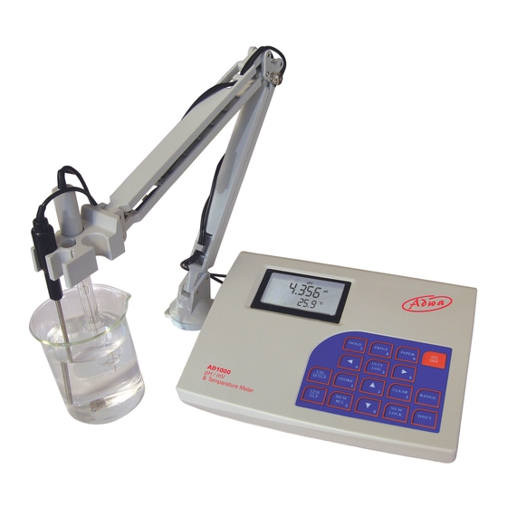
USER MANUAL
AD1000 and AD1020
pH/mV/ISE/Temperature
Bench Meters
w w w . a d w a i n s t r u m e n t s . c o m
1
Table of
Contents
Previous
Page
Next
Page
1
2
3
4
5
Advertisement
Table of Contents
Need help?
Do you have a question about the AD1000 and is the answer not in the manual?
Ask a question
Questions and answers
Related Manuals for ADWA AD1000
Measuring Instruments ADWA AD 330 User Manual
Ec/tds/temperature portable meter (18 pages)
Measuring Instruments ADWA AD 630 User Manual
Do & temperature waterproof meter with galvanic probe (40 pages)
Measuring Instruments ADWA AD1020 User Manual
Ph/mv/ise/temperature meter (76 pages)
Measuring Instruments ADWA AD 130 User Manual
Ph/mv/temperature portable meter (18 pages)
Measuring Instruments ADWA AD331 User Manual
Waterproof portable meters for ec and tds measurements (20 pages)
Measuring Instruments ADWA AD332 User Manual
Waterproof portable meters for ec and tds measurements (20 pages)
Measuring Instruments ADWA AD31 User Manual
Waterproof ec/tds testers (2 pages)
Measuring Instruments ADWA AD32 User Manual
Waterproof ec/tds testers (2 pages)
Measuring Instruments ADWA AD 3000 User Manual
Ec/tds/temperature bench meter (18 pages)
Measuring Instruments ADWA AD100 Instructions
Ph meter (2 pages)
Measuring Instruments ADWA AD 310 User Manual
(14 pages)
ADWA AD33, AD34, AD35, AD36 - Waterproof EC And TDS Tester Manual
(article)
Measuring Instruments ADWA AD110 User Manual
Ph/c and ph/mv/c meters (20 pages)
Measuring Instruments ADWA AD111 User Manual
Ph/c and ph/mv/c meters (20 pages)
Measuring Instruments ADWA ECO406 User Manual
Tds monitors (2 pages)
This manual is also suitable for:
Ad1020
Table of Contents
Print
Rename the bookmark
Delete bookmark?
Delete from my manuals?
Login
Sign In
OR
Sign in with Facebook
Sign in with Google
Upload manual
Upload from disk
Upload from URL


Need help?
Do you have a question about the AD1000 and is the answer not in the manual?
Questions and answers