Dell Z9000 Manual
Z9000 system
Hide thumbs
Also See for Z9000:
- Configuration manual (968 pages) ,
- Installing (52 pages) ,
- Quick start manual (27 pages)
Table of Contents
Advertisement
Quick Links
Advertisement
Table of Contents

Related Manuals for Dell Z9000


Summary of Contents for Dell Z9000
- Page 1 Installing the Z9000 System...
- Page 2 WARNING: A WARNING indicates a potential for property damage, personal injury, or death. Copyright © 2014 Dell Inc. All rights reserved. This product is protected by U.S. and international copyright and intellectual property laws. Dell ™...
-
Page 3: Table Of Contents
..............................12 Power ........................... 13 Storing Components 4 Install the Z9000..................... 15 ................16 Installing the Z9000 Chassis in a Rack or Cabinet ....................17 Attaching the Mounting Brackets ................17 Installing the System into a Rack or Cabinet ....................18 Installing the Rear Mounting Brackets ....................... - Page 4 ........................24 Installing a Power Supply ..................... 24 Installing a New AC Power Supply ..................... 25 Installing a New DC Power Supply ......................25 Replacing an AC Power Supply ......................26 Replacing a DC Power Supply 6 Fans..........................27 ............................27 Components ........................
-
Page 5: About This Guide
About this Guide This guide provides site preparation recommendations, step-by-step procedures for rack mounting and desk mounting, inserting optional modules, and connecting to a power source. CAUTION: To avoid electrostatic discharge (ESD) damage, wear grounding wrist straps when handling this equipment. WARNING: Only trained and qualified personnel can install this equipment. -
Page 6: Related Documents
Related Documents For more information about the Z9000 system, refer to the following documents. • Dell Networking OS Configuration Guide for the Z9000 System • Dell Networking OS Command Line Reference Guide for the Z9000 System • Dell Networking OS Release Notes for the Z9000 System... -
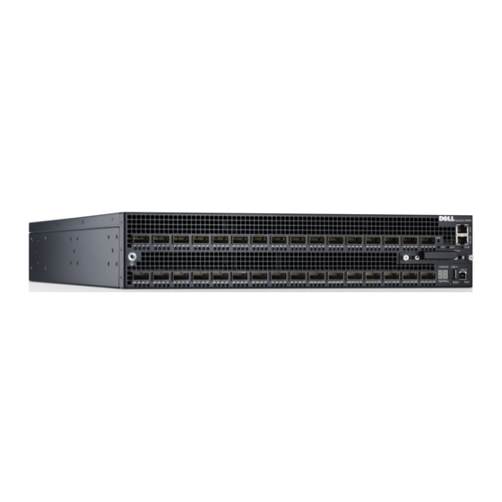
Page 7: The Z9000 System
It is a two-rack unit (RU) chassis that supports 32 ports of 40GE QSFP+ or 128 ports of 10GE SFP+ (with breakout cables). The Z9000 includes an RS-232 console port and a management port for system access. -
Page 8: Features
Figure 2. The Z9000 System PSU-Side View Features The Z9000 offers the following. • Z9000 CPU and switch processor • Hot-swappable redundant power supply • 19 inch rack-mountable • Standard 2U chassis height • Up to 128K MAC address entries supported with hardware assisted aging •... -
Page 9: System Status
You can also view status information through the command line interface (CLI) show commands and with simple network management protocol (SNMP) traps. For more information about these options, refer to the Dell Networking OS Command Line Reference Guide for the Z9000 System and the Dell Networking OS Configuration Guide for the Z9000 System. - Page 10 MASTER The Z9000 System...
-
Page 11: Site Preparations
National Electric Code (NEC) applies For more information about Z9000 specifications, refer to Specifications. NOTE: Install the Z9000 system into a rack or cabinet before installing any optional components. Site Selection The following section describes where to install Dell Networking equipment. -
Page 12: Rack Mounting
Reversed — airflow is from the power supply to the I/O panel. The grab-handle is labeled Intake. For proper ventilation, position the Z9000 in an equipment rack (or cabinet) with a minimum of 5 inches (12.7 cm) of clearance around the exhaust vents. When you install two Z9000 systems near each other, position the two chassis at least 5 inches (12.7 cm) apart to permit proper airflow. -
Page 13: Storing Components
WARNING: Electrostatic discharge (ESD) damage can occur when components are mishandled. Always wear an ESD-preventive wrist or heel ground strap when handling the Z9000 and its accessories. After you remove the original packaging, place the Z9000 and its components on an antistatic surface. -
Page 15: Install The Z9000
To install the Z9000 system, Dell Networking OS recommends completing the installation procedures in the order presented in this chapter. Always handle the Z9000 and its components with care. Avoid dropping the system or its field replaceable units (FRUs). This chapter describes the installation procedures as follows:... -
Page 16: Installing The Z9000 Chassis In A Rack Or Cabinet
Installing the Z9000 Chassis in a Rack or Cabinet The Z9000 is shipped with mounting brackets (rack ears) and the required screws for rack or cabinet installation. The brackets are enclosed in a package with the system. To attach the brackets to the system, follow these steps: Take the brackets and screws out of their packaging. -
Page 17: Attaching The Mounting Brackets
Attaching the Mounting Brackets The Z9000 ships with mounting brackets (rack ears) and the required screws for rack or cabinet installation. The brackets are enclosed in a package with the system. Attach the brackets to the system as follows: Take the brackets and screws out of their packaging. -
Page 18: Installing The Rear Mounting Brackets
To attach the ground cable to the chassis, use a single M4x0.7 screw. The cable itself is not included with the Z9000. To properly ground the chassis, Dell Networking OS recommends using a 6AWG one-hole lug, #10 hole size, 63" spacing (not included in shipping). The one- hole lug must be a UL recognized, crimp-type lug. -
Page 19: Installing The Qsfp+ Optics
WARNING: ESD damage can occur if components are mishandled. Always wear an ESD- preventive wrist or heel ground strap when handling the Z9000 and its components. WARNING: When working with optical fibers, follow all warning labels and always wear eye protection. -
Page 20: Removing The Qsfp+ Optics
The Z9000 includes a solid state drive (SSD) that acts as another storage device. The SSD ships installed in the Z9000 system and is located in a slot on the lower-right area on the I/O side (shown in the following illustration). -
Page 21: Removing The Solid State Drive
Finger tighten the retaining screws. Restart the system. Supply Power and Power Up the System Supply power to the Z9000 after it is mounted in a rack or cabinet. Dell Networking OS recommends re-inspecting your system prior to powering up. Verify that: •... -
Page 22: Power Up Sequence
To add AC power, connect the power cord plug to each AC power connector. Make sure that the power cord is secure. As soon as the cable is connected between the Z9000 system and the power source, the system is powered-up; there is no on/off switch. -
Page 23: Power Supplies
The PSUs in the Z9000 are field replaceable. When both power supplies are installed and running, you can remove one power supply without interrupting traffic. Power Supply 0 (PSU0) is on the top of the Z9000; power supply 1(PSU1) is on the bottom of the Z9000 system. -
Page 24: Installing A Power Supply
To install power supply, follow these steps. NOTE: The PSU slides into the slot smoothly. Do not force a PSU into a slot as this action may damage the PSU or the Z9000 chassis. Take the PSU out of the shipping box. -
Page 25: Installing A New Dc Power Supply
Replacing an AC Power Supply To replace a power supply, follow these steps. NOTE: The PSU slides into the slot smoothly. Do not force a PSU into a slot as this action may damage the PSU or the Z9000 chassis. Power Supplies... -
Page 26: Replacing A Dc Power Supply
PSU. To request a hardware replacement, refer to Technical Support. NOTE: If you use a single PSU, install a blank plate in the other PSU slot. Dell Networking OS recommends using power supply 1 (PSU1) as the blank plate slot. Disconnect the power cable from the PSU. -
Page 27: Fans
(for example, new equipment installation). CAUTION: If the wrong fan air flow is ordered or if the wrong fans are received with your Z9000, the entire Z9000 must be replaced. Normal fans cannot be swapped with reverse air flow fans;... - Page 28 To install a fan module, follow these steps. Twist the latching screws so that the fan screen detaches from the system, as shown in the following illustration. Figure 7. Illustration for installing a fan module Latching Screw Fan Screen Remove the screen and set it aside. Take the fan module out of the shipping box.
-
Page 29: Replacing A Fan Module
Replacing a Fan Module To replace a fan module, follow these steps. Twist the latching screws so that the fan screen detaches from the system. Figure 8. Illustration for replacing a Fan module Screw Grab Handle Fan Module Remove the fan screen and set it aside. Loosen the securing screw on the side of the module. -
Page 31: Console Ports
The USB-B ports act exactly the same as the console port. The terminal settings are the same for both access ports. Accessing the RJ-45 Console Port (RS-232) The RS-232/RJ-45 console port is labeled on the upper right side of the Z9000 chassis (the I/O side) (as shown in the following illustration). Figure 9. RJ-45/RS-232 Console Port Connector To access the RJ-45/RS-232 console port, follow these steps. -
Page 32: Access The Rj-45 Console Port With A Db-9 Adapter
Access the RJ-45 Console Port with a DB-9 Adapter If the DTE has a DB-9 interface, you can connect to the console using an RJ-45 to DB-9 adapter along with the RJ-45 rollover cable. The following table lists the pin assignments. Table 1. -
Page 33: Accessing The Solid State Drive
The SSD is field replaceable and supports drives that use 12 Volts and/or 5.0 Volts. Be sure to use only drives that Dell Networking supports. NOTE: You cannot hot-swap the SSD. You must reboot the Z9000 to recognize a new or reseated SSD. -
Page 34: Components
Use the grab handle to slide the SSD into the slot. Restart the system. Included here are some key commands supported by the SSD. For a complete description of the commands supported by the SSD, refer to the Dell Networking Command Line Reference Guide for the Z9000 System. Console Ports... -
Page 35: Viewing Files On The Ssd
Destination file name [FTOS-ZB-8.3.11.0.bin.bin]: !!!!!!!!!!!!!!!!!!!!!!!!!!!!!!!!!!!!!!!!!!!!!!!!!!!!!!!!!!!!!!!! 26292881 bytes successfully copied Copy from the internal flash to the SSD. Dell#copy flash: slot0:boot-image Destination file name [FTOS- ZB-8.3.11.0.bin.bin]: !!!!!!!!!!!!!!!!!!!!!!!!!!!!!!!!!!!!!!!!!!!!!!!!!!!!!!!!!! !!!!!! 26292881 bytes successfully copied Removing Files From the SSD To remove files from the SSD, use the delete command. -
Page 37: Specifications
Specifications This chapter lists the Z9000 specifications. Chassis Physical Design Table 2. Chassis Physical Design Parameter Specifications Height 3.48 inches (8.8 cm) Width 17.32 inches (44.0 cm) Depth 24.00 inches (61.00 cm) Chassis weight 50.3 lbs (approx.) (22.8 kg) Front: 5-inches (12.7 cm) Rack clearance required Rear: 5-inches (12.7 cm) -
Page 38: Ieee Standards
Properly shielded and grounded cables and connectors must be used in order to meet FCC emission limits. Dell Networking is not responsible for any radio or television interference caused by using other than recommended cables and connectors or by unauthorized changes or modifications in the equipment. -
Page 39: European Union Emc Directive Conformance Statement
This product is in conformity with the protection requirements of EU Council Directive 2004/108/EC on the approximation of the laws of the Member States relating to electromagnetic compatibility. Dell Networking can not accept responsibility for any failure to satisfy the protection requirements resulting from a non-recommended modification of this product, including the fitting of non-Dell Networking option cards. -
Page 40: Korean Certification Of Compliance
WARNING: Use the AC power cords with Dell Networking equipment only. Do not use Dell Networking AC power cords with any unauthorized hardware. This is Class A product based on the standard of the Voluntary Control Council For Interference by Information Technology Equipment (VCCI). -
Page 41: Electromagnetic Compatibility (Emc)
Networking encourages owners of information technology (IT) equipment to responsibly recycle their equipment when it is no longer needed. Dell Networking offers a variety of product return programs and services in several countries to assist equipment owners in recycling their IT products. -
Page 42: Removing The Sd Card
EEE on the environment and human health due to the potential presence of hazardous substances in EEE. Dell Networking products, which fall within the scope of the WEEE, are labeled with the crossed-out wheelie-bin symbol, as shown above, as required by WEEE. -
Page 43: Replacing The Battery
The lithium battery is not field replaceable. Only authorized personal should remove and replace the battery. If the battery requires replacement, contact Dell Networking Technical Support. WARNING: ESD damage can occur if components are mishandled. Always wear an ESD- preventive wrist or heel ground strap when handling the S4810–ON and its components. As with all electrical devices of this type, take all the necessary safety precautions to prevent injury when installing this system. - Page 44 Customer participation is important to minimize any potential effects of batteries and accumulators on the environment and human health due to the potential presence of hazardous substances. For proper collection and treatment, contact your local Dell Networking representative. Figure 16. The European WEEE Symbol For California: •...
- Page 45 • Refer to http://www.dtsc.ca.gov/hazardouswaste/perchlorate The foregoing notice is provided in accordance with California Code of Regulations Title 22, Division 4.5 Chapter 33. Best Management Practices for Perchlorate Materials. Specifications...
-
Page 47: Technical Support
Requesting a Hardware Replacement The iSupport Website iSupport provides a range of documents and tools to assist you with effectively using Dell Networking equipment and mitigating the impact of network outages. Through iSupport you can obtain technical information regarding Dell Networking products, access to software upgrades and patches, and open and manage your Technical Assistance Center (TAC) cases. -
Page 48: Requesting A Hardware Replacement
Contacting the Technical Assistance Center). • Contacting Dell Networking directly by email or by phone (refer to Contacting the Technical Assistance Center). Provide the following information when using email or phone: – Part number, description, and serial number of the component.
Need help?
Do you have a question about the Z9000 and is the answer not in the manual?
Questions and answers