Dell EMC PowerSwitch Z9100–ON Installation Manual
Hide thumbs
Also See for EMC PowerSwitch Z9100–ON:
- Installation manual (45 pages) ,
- Deployment manual (78 pages) ,
- Installation manual (43 pages)
Table of Contents
Advertisement
Quick Links
Advertisement
Table of Contents

Related Manuals for Dell EMC PowerSwitch Z9100–ON


Summary of Contents for Dell EMC PowerSwitch Z9100–ON
- Page 1 Dell EMC PowerSwitch Z9100–ON Installation Guide March 2021 March 2021 Rev. A06...
- Page 2 A WARNING indicates a potential for property damage, personal injury, or death. © 2015 - 2021 Dell Inc. or its subsidiaries. All rights reserved. Dell, EMC, and other trademarks are trademarks of Dell Inc. or its subsidiaries. Other trademarks may be trademarks of their respective owners.
-
Page 3: Table Of Contents
Contents Chapter 1: About this guide......................5 Related documents................................5 Chapter 2: The Z9100–ON switch....................6 Introduction...................................6 Features....................................7 Physical dimensions................................7 LED display.................................... 7 LED behavior...................................8 Prerequisites..................................10 Z9100–ON configurations..............................10 Switch status..................................11 Luggage tag..................................11 Chapter 3: Site preparations......................12 Site selection..................................12 Cabinet placement................................ - Page 4 European Union EMC Directive Conformance statement..................41 Japan VCCI Compliance for Class A Equipment......................42 Korean certification of compliance..........................42 Safety Standards and Compliance Agency certifications..................43 Electromagnetic Compatibility ............................43 Product recycling and disposal............................44 Chapter 10: Dell EMC support......................45 Contents...
-
Page 5: Chapter 1: About This Guide
● Dell Networking Getting Started Guide for the Z9100–Open Networking (ON) System ● Dell Networking Release Notes for the Z9100–Open Networking (ON) System ● Dell Networking Command Line Reference Guide for the Z9100–Open Networking (ON) System ● Dell Networking Configuration Guide for the Z9100–Open Networking (ON) System ●... -
Page 6: Chapter 2: The Z9100-On Switch
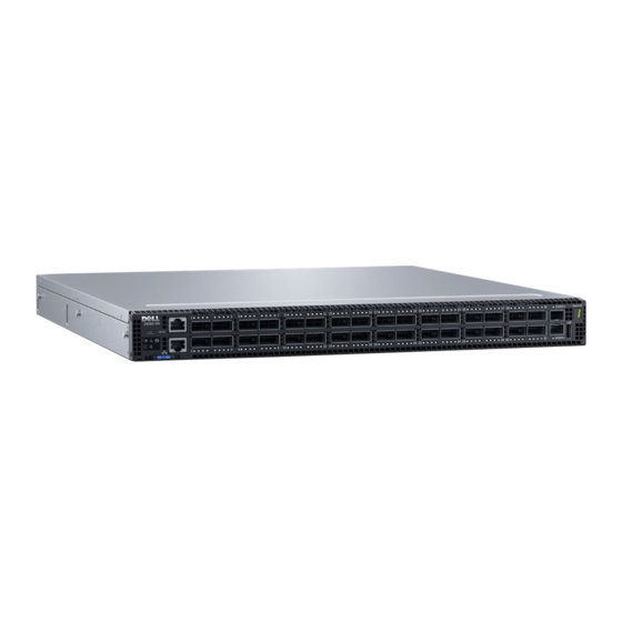
The Z9100–ON switch The following sections describe the Dell EMC Z9100–ON switch: Topics: • Introduction • Features • Physical dimensions • LED display • Prerequisites • Z9100–ON configurations • Switch status • Luggage tag Introduction The Z9100-ON is a one rack unit compact 10/25/40/50/100 GbE switch. The switch includes 32 fixed quad form-factor pluggable 28 (QSFP28) optics for 40/100 GbE aggregation and 10/25/40/50 GbE top-of-rack (ToR) and end-of-row (EoR) applications. -
Page 7: Features
Figure 3. Z9100–ON PSU-side view 1. Fan modules 2. Power supply units Features The Z9100–ON offers the following features. ● QSFP ports support 10/25/40/50/100 GbE ● Two 1000M/10G SFP+ ports ● One micro universal serial bus (MicroUSB-B) console port ● One 2.0 USB Type-A port for additional file storage ●... -
Page 8: Led Behavior
LED behavior The following Z9100–ON switch LED behavior is seen during open networking installation environment (ONIE) operations: Figure 4. Z9100–ON LEDs 1. Master LED 2. Switch LED 3. Locator LED 4. QSFP28 LED 5. SFP+ LED 6. Stack ID 7. SFP+ LED 8. - Page 9 Table 1. Z9100–ON LED behavior (continued) Description Fan LED ● Off—No powe.r ● Solid green—Fan powered and running at the expected RPM. ● Flashing amber—Fan failed or incompatible airflow direction, PSU or fan trays with differing airflows. Power LED ● Off—No power. ●...
-
Page 10: Prerequisites
Prerequisites The following is a list of components needed for successful installation of the Z9100-ON: NOTE: Detailed installation instructions for the Z9100-ON are provided in Site Preparations Install the Z9100-ON. ● Z9100–ON switch, or multiple switches if stacking ● AC or DC country- and regional-specific cables. Used to connect the AC or DC power source to each of the switches’ AC or DC power supplies. -
Page 11: Switch Status
Switch status You can view Z9100–ON status information using the light emitting diodes (LEDs). Luggage tag The Z9100–ON switch has a pull-out tag, known as a luggage tag, on the I/O-side of the switch. The luggage tag includes switch ID information. Figure 5. -
Page 12: Chapter 3: Site Preparations
Storing components Site selection Install Dell EMC equipment in restricted access areas. A restricted access area is one in which service personnel can only gain access using a special tool, lock, key or other means of security. The authority responsible for the location must control the site access. -
Page 13: Rack Mounting
Module power is software controlled. You do not see module LEDs when the switch powers up in ONIE. Storing components If you do not install your Z9100–ON and components immediately, Dell EMC recommends properly storing the switch and all optional components by following these guidelines: ●... - Page 14 NOTE: ESD damage can occur when components are mishandled. Always wear an ESD-preventive wrist or heel ground strap when handling the Z9100–ON and its accessories. After you remove the original packaging, place the Z9100–ON and its components on an antistatic surface. Site preparations...
-
Page 15: Chapter 4: Nebs Compliance
Your switch includes two installed M3 screws on the lower-left side of your switch. Your switch also includes an assembled UL-certified GND lug with bracket, packaged separately. If any parts are missing, contact your Dell EMC sales representative. NEBS compliance... - Page 16 Figure 6. GND lug assembly 1. Remove the two installed M3 screws from the lower-left side of your switch. NOTE: Keep these screws. 2. Remove the bracket assembly from the shipping bag. 3. Clean the bracket and lug surfaces thoroughly, and apply an anti-oxidant solution to the mating surfaces. 4.
- Page 17 Figure 8. GND lug assembly attached 6. Install your switch into your rack using the Z9100-ON Installation instructions. NEBS compliance...
-
Page 18: Chapter 5: Z9100-On Installation
● Warranty and Support Information Ground cable NOTE: For AC-powered switches, although the third conductor of the AC power cord provides a ground path, Dell EMC recommends grounding your switch with a dedicated ground wire. NOTE: For DC-powered switches, the only way to safely ground your switch is to attach a dedicated ground wire. -
Page 19: Rack Or Cabinet Installation
In both configurations, the ground cable is not included. To properly ground the switch, Dell EMC recommends a one- or two-hole lug, M3 or M4 hole size. The switch hole lugs must be a UL-recognized, crimp-type lug. must be made of copper. Do not use aluminum conductors. -
Page 20: Readyrails Installation
ReadyRails installation The ReadyRails rack mounting system is provided to easily configure your rack for installation of your Z9100–ON switch. You can install the ReadyRails system using the 1U tool-less method or one of three possible 1U tooled methods. The tooled installation methods include two-post flush mount, two-post center mount, or four-post threaded. -
Page 21: Two-Post Center-Mount Configuration
Figure 10. Two-post flush-mount configuration 2. Attach one rail to the front post flange with two user-supplied screws, item 2. 3. Slide the plunger bracket forward against the vertical post and secure the plunger bracket to the post flange with two user-supplied screws, item 3. -
Page 22: Four-Post Threaded Configuration
Figure 11. Two-post center-mount configuration 2. Slide the back bracket towards the post. Secure it to the post flange with two user-supplied screws, item 2. 3. Repeat this procedure for the second rail. Four-post threaded configuration CAUTION: To be NEBS Earthquake Z4-compliant, you must remove the tool-less latch castings described in Step 1. -
Page 23: Z9100-On Switch Installation
Figure 12. Four-post threaded configuration 2. For each rail, attach the front and back flanges to the post flanges with two user-supplied screws at each end, item 2. Z9100-ON switch installation You can mount the switch in the 1U front-rack or 1U two-post flush and center configurations. The following is an example of a front-rack configuration. - Page 24 Figure 13. Switch rail attachment 2. After you install both rails, line them up on the ReadyRails. Slide the switch in until it is flush with front of rack. About three inches before you fully insert your switch, the rail locking feature engages to keep the switch from inadvertently sliding out and falling.
-
Page 25: Optics Installation
Do not jerk or tug repeatedly on the tab. Port connectivity Dell EMC recommends that you distribute port groups across all four port pipes. The Z9100-ON switch has four port pipes, also known as packet processing pipelines. For the best buffer resource usage, distribute the functional port groups, such as downlinks, uplinks, interchassis links, LAGs, and ECMP, across all four port pipes—... -
Page 26: Switch Power Up
● If you are using Dell EMC software, see switch documentation at www.dell.com/support. ● If you need ONIE information, see ONIE documentation at www.onie.org. Switch replacement The following steps describe removing and replacing a switch. For further assistance when replacing a switch, contact your Dell EMC support representative. NOTE: ESD damage can occur when components are mishandled. - Page 27 If you are using the fan trays or PSUs in the replacement switch, remove them from the switch. 5. Unpack the new switch. For more information, see Unpack. 6. Confirm that the software version of the replacement switch is the same as the previously installed switch. show os-version If the software versions do not match, upgrade the replacement switch software using the procedure included with the firmware download.
-
Page 28: Chapter 6: Power Supplies
Power supplies The switch ships with two AC or DC power supplies. The power supplies have two air-flow directions, normal and reverse. Normal is from the I/O-side to the PSU-side. Reverse is from the PSU-side to the I/O-side. Two PSUs are required for full redundancy, but the switch can operate with a single PSU. The PSUs are field replaceable. -
Page 29: Ac Or Dc Power Supply Installation
WARNING: Prevent exposure and contact with hazardous voltages. Do not attempt to operate this switch with the safety cover removed. CAUTION: Remove the power cable from the PSU before removing the PSU. Also, do not connect the power cable before you insert the PSU in the switch. NOTE: To comply with the GR-1089 Lightning Criteria for Equipment Interfacing with AC or DC Power Ports, use an external surge protection device (SPD) at the AC or DC input of the router. - Page 30 Figure 18. DC power connector and wiring block 1. DC wire RTN 2. DC power connector 3. Captive screws (2) 4. Orange tab 5. PSU status LED 6. DC power socket 7. DC wire –48V Figure 19. DC power connector ground 1.
-
Page 31: Ac Or Dc Power Supply Replacement
NOTE: If a PSU fails, you must replace the entire unit. There are no field serviceable components in the PSU. To request a hardware replacement, see Dell Support. NOTE: If you use a single PSU, install a blank plate in the other PSU slot. If you are only using one power supply, install the power supply in the first slot, PSU1. -
Page 32: Chapter 7: Fans
Fans The Z9100–ON comes from the factory with two PSUs and five fan modules installed in the switch. The fan modules and PSUs, which have integrated fans, are hot-swappable. In addition to the power supply modules, you can order and install fan modules separately. The Z9100-ON requires a minimum of four running fans. -
Page 33: Fan Module Installation
Fan module installation The fan modules are field replaceable. Module slot 1 is on the left side of the switch; module slot 5 is on the right side of the switch. CAUTION: DO NOT mix airflow directions. All reverse or normal fans must use the same airflow direction. If you mix the airflow direction, the switch detects the discrepancy, issues an alarm, and may autoshutdown to avoid heat damage to the components. - Page 34 3. Slide the existing filter upwards to remove it from the module. 4. Replace the filter with a new filter of the same size. 5. Repeat for the remaining modules that need the filter replaced. Fans...
-
Page 35: Chapter 8: Management Ports
Management ports The Z9100–ON switch provides several ports for management and storage. Topics: • RS-232 console port access • MicroUSB-B console port access • USB storage • Before you install an OS • Switch check RS-232 console port access The RS-232 console port is on the I/O-side of the Z9100-ON switch. Figure 22. -
Page 36: Microusb-B Console Port Access
MicroUSB-B console port access The MicroUSB type B console port is on the I/O side of the switch. NOTE: The Z9100-ON switch uses the Silicon Labs CP2102 USB-B chip. To find the correct USB-B universal asynchronous receiver-transmitter (UART) driver, see https://www.silabs.com/products/development-tools/software/ usb-to-uart-bridge-vcp-drivers. -
Page 37: Before You Install An Os
For more information, see the Open Networking Hardware Diagnostic Guide for the Z9100–ON System. NOTE: After you have securely installed and powered on the Z9100-ON, to configure your switch, see your third-party ONIE-compatible OS or the Dell EMC OS documentation. Management ports... -
Page 38: Switch Check
Switch check To confirm that ONIE is working properly, use the onie-sysinfo command. Run the onie-sysinfo command at the ONIE prompt. ONIE:/ # onie-sysinfo x86_64-dell_z9100_c2538-r0 ONIE:/ # onie-sysinfo –c (Machine arch) x86_64 ONIE:/ # onie-sysinfo –v (ONIE Version programmed) 3.23.1.0 ONIE:/ # ONIE:/ # uname -a Linux onie 3.2.35-onie+ #1 SMP Tue Dec 9 17:08:16 PST 2014 x86_64 GNU/Linux... -
Page 39: Chapter 9: Specifications
Specifications This topic lists the Z9100–ON specifications. CAUTION: Operate the product at an ambient temperature not higher than 113°F (45°C). CAUTION: Lithium Battery Caution: There is a danger of explosion if the battery is incorrectly replaced. Replace only with same or equivalent type of battery. Dispose of the batteries according to the manufacturer's instructions. -
Page 40: Ieee Standards
Table 8. Environmental parameters (continued) Parameter Specifications Storage temperature –40° to 158°F (–40° to 70°C) Storage humidity 5 percent to 90 percent, non-condensing Maximum thermal output 292.42 BTU/hr 85.7 W Maximum operational altitude 10,000 feet (3,048 meters) Maximum non-operational altitude 39,370 feet (12,000 meters) Shock SV0115 —... -
Page 41: European Union Emc Directive Conformance Statement
Properly shielded and grounded cables and connectors must be used in order to meet FCC emission limits. Dell EMC is not responsible for any radio or television interference caused by using other than recommended cables and connectors or by unauthorized changes or modifications in the equipment. -
Page 42: Japan Vcci Compliance For Class A Equipment
Equipment (VCCI). If this equipment is used in a domestic environment, radio disturbance may arise. When such trouble occurs, the user may be required to take corrective actions. NOTE: Use the AC power cords with Dell EMC equipment only. Do not use Dell EMC Force10 AC power cords with any unauthorized hardware. Figure 25. Japan warning label Korean certification of compliance Figure 26. -
Page 43: Safety Standards And Compliance Agency Certifications
Figure 27. Korean package label Safety Standards and Compliance Agency certifications ● IEC 62368-1, 2nd Edition ● CUS UL 60950-1, 2nd Edition ○ Meets or exceeds Hi Pot and Ground Continuity testing per UL 60950-1. ● AS/NZS 60950 ● CSA 60950-1-03, 2nd Edition ●... -
Page 44: Product Recycling And Disposal
EEE on the environment and human health due to the potential presence of hazardous substances in EEE. Dell EMC products, which fall within the scope of the WEEE, are labeled with the crossed-out wheelie-bin symbol, as shown above, as required by WEEE. -
Page 45: Chapter 10: Dell Emc Support
Dell EMC support The Dell EMC support site provides documents and tools to help you effectively use Dell EMC equipment and mitigate network outages. Through the support site you can obtain technical information, access software upgrades and patches, download available management software, and manage your open cases. The Dell EMC support site provides integrated, secure access to these services.
Need help?
Do you have a question about the EMC PowerSwitch Z9100–ON and is the answer not in the manual?
Questions and answers