
Related Manuals for Fronius IG Plus 30 V-1


Summary of Contents for Fronius IG Plus 30 V-1
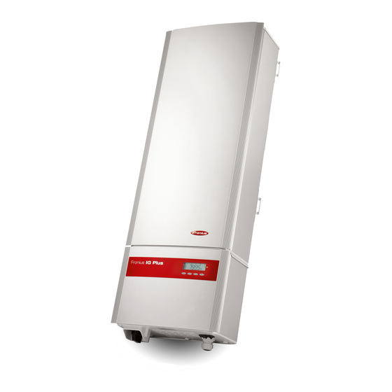
- Page 1 Fronius IG Plus Operating Instructions Inverter for grid-connected photo- 30 V / 35 V / 50 V / 70 V voltaic systems 100 V / 120 V / 150 V 42,0426,0062,EA 02/2011...
- Page 3 Thank you for the trust you have placed in our company and congratulations on buying this high-quality Fronius product. These instructions will help you familiarize yourself with the product. Reading the instructions carefully will enable you to learn about the many different features it has to offer.
- Page 5 Galvanic isolation..........................Monitoring the Grid ..........................Warning notices affixed to the device ....................Warning notice on the wall bracket ....................... The Fronius IG Plus Unit in the PV System ....................General ..............................Tasks ..............................Converting DC to AC Current .......................
- Page 6 Fronius IG Plus Installation ........................Attaching the wall bracket ........................Lifting the Fronius IG Plus........................Fronius IG Plus installation ........................Connecting the Fronius IG Plus to the Public Grid (AC) ................Monitoring the Grid ..........................Installations with Several Inverters ....................... AC-Side Terminals..........................
- Page 7 General ..............................Solar Module Ground at Negative Pole ....................Solar Module Ground at Negative Pole for Fronius IG Plus ..............Safety..............................Setting inverters for grounded solar modules ..................Solar Module Ground: Inserting Fuse or "100 kohm Grounding Kit" Option......... Opening Fronius IG Plus for Service/Maintenance................
- Page 8 Displaying Status Codes........................127 Normal Operation Status Codes ......................127 Total Failure ............................127 Status Codes on Fronius IG Plus with Several Power Stage Sets ............127 Class 1 Status Codes ........................... 128 Class 3 status codes..........................130 Class 4 status codes..........................132...
- Page 9 Transport............................... 159 When making a warranty claim, attention should be paid to the following..........159 Scope and Validity of Manufacturer's Warranty ..................160 Exceptions to the Fronius manufacturer's warranty ................160 Geographical Validity ..........................160 Other Legal Information ........................160 Disposal ..............................
-
Page 11: Safety Rules
Safety rules Safety Rules Ex- DANGER! Indicates an imminently hazardous situation which, if not avoided, will planation result in death or serious injury. WARNING! Indicates a potentially hazardous situation which, if not avoided, will result in death or serious injury. CAUTION! Indicates a potentially harmful situation which, if not avoided, may re- sult in minor and moderate injury or property damage. -
Page 12: Utilization In Accordance With "Intended Purpose
Your personal safety is at stake! Utilization in Ac- The device is to be used exclusively for its intended purpose. cordance with "Intended Pur- Utilization for any other purpose, or in any other manner, shall be deemed to pose" be "not in accordance with the intended purpose." The manufacturer shall not be liable for any damage resulting from such improper use. -
Page 13: Data Regarding Noise Emission Values
Safety Measures When installing devices with openings for cooling air, ensure that the cooling air can enter at the Installation and exit unhindered through the vents. Only operate the device in accordance with the de- Location gree of protection shown on the rating plate. Data Regarding The inverter generates a maximum sound power level of <... -
Page 14: Electrical Installations
In this case, the operator or the person using the device should check whether or not the device is allowed to be connected, where appropriate through dis- cussion with the power supply company. Electrical Installa- Electrical installations must only be carried out according to relevant national tions and local standards and regulations. -
Page 15: Backup
Backup The user is responsible for backing up any changes made to the factory set- tings. The manufacturer accepts no liability for any deleted personal settings. Copyright Copyright of these operating instructions remains with the manufacturer. Text and illustrations are technically correct at the time of going to print. The right to make modifications is reserved. -
Page 17: General Information
General Information... -
Page 19: Protection Of Persons And Equipment
Protection of Persons and Equipment Safety WARNING! If the equipment is used or tasks are carried out incorrectly, serious injury or damage may result. Only qualified personnel are authorized to install your inverter and only within the scope of the respective technical regulations. It is essential that you read the "Safety regulations"... - Page 20 Safety symbols: Risk of serious injury and damage due to incorrect operation...
- Page 21 Do not use the functions described until you have thoroughly read and under- stood the following documents: these operating instructions all operating instructions for system components of the photovoltaic sys- tem, especially the safety rules Dangerous electrical voltages Text of warning notices: WARNING! The connection area should only be opened by a licensed electrician.
-
Page 22: The Fronius Ig Plus Unit In The Pv System
The Fronius IG Plus Unit in the PV System General The solar inverter is the highly complex link between the solar modules and the public grid. Tasks The main tasks of the inverter include: Converting DC to AC current Fully automatic operational management... -
Page 23: Kohm Grounding Kit Option
Various large-format displays Fronius Personal Display Actuators (e.g.: relays, alarms) Interface cards System upgrades are available as plug-in cards. Forced Ventila- The inverter's temperature-controlled, variable-speed fan with ball-bearing support pro- tion vides: optimal inverter cooling efficiency increases cooler components, thus improving service life... -
Page 25: Installation And Startup
Installation and Startup... -
Page 27: Fronius Ig Plus Installation And Connection
Power stage set(s) Connection area Overview ‘Fronius IG Plus Installation and Connection’ contains the following sections: Choosing the Location Fronius IG Plus Connection Options Knockouts on the Fronius IG Plus Fronius IG Plus Installation... -
Page 28: Choosing The Location
Choosing the Location Choosing the Lo- Please note the following criteria when choosing a location for the inverter: cation, General It should only be installed on a stable, vertical wall Max. ambient temperatures: -20 °C / +55 °C Relative humidity: 0 - 95 % For use at altitudes above sea level: up to 2000 m There should be a 200 mm (7.8 in) clearance on both sides of the inverter for the cool air vents. - Page 29 Choosing a loca- Because of its degree of protection, the inverter is not susceptible to splash water from tion for outdoor any direction. installation However the manufacturer recommends, if possible, not to expose the inverter to direct weathering, in order to prevent water deposits caused by rain or snow. In order to protect the display, the inverter should not be exposed to direct sunlight.
-
Page 30: Fronius Ig Plus Connection Options
Fronius IG Plus Connection Options Fronius IG Plus connection op- tions Item Description Fuse cover (6 x for string fuses, 1 x for the solar module ground fuse) Jumper slot SMON DC+ main switch wire 6 DC+ fuse holders Jumper slot SMOFF... - Page 31 Item Description (16) Strain relief for solar module strings (17) 6 DC+ terminals (18) DC main switch...
-
Page 32: Knockouts On The Fronius Ig Plus
Knockouts on the Fronius IG Plus General The inverter contains several knockouts of different sizes. When knocked out, the open- ings are used for the inputs of various wires. Knockouts on the Fronius IG Plus for wire inputs Item Description 2 cable inputs for M32 metric screw joint (for DC cables with a cross section >... -
Page 33: Fronius Ig Plus Installation
Therefore, these dowels and screws are not part of the scope of supply for the inverter. The system installer is responsible for selecting the proper dowels and screws. NOTE! The Fronius IG Plus should only be installed upright on the wall. min. 50 mm min. 2 in. -
Page 34: Fronius Ig Plus Installation
Vacuum lifting pads are not part of the scope of delivery for the inverter. Weight information for the connection area and power stage set: Inverter Connection area Power stage set Fronius IG Plus 30 V-1 9,85 kg 13,95 kg Fronius IG Plus 35 V-1 9,85 kg... - Page 35 Use the screws in the bag attached to the wall bracket to secure the power stage set to the connection area.
-
Page 36: Connecting The Fronius Ig Plus To The Public Grid (Ac)
Connecting the Fronius IG Plus to the Public Grid (AC) Monitoring the IMPORTANT! The resistance in the leads to the AC-side connection terminals must be as Grid low as possible for optimal functioning of grid monitoring. Installations with For larger photovoltaic systems, it is possible to connect several inverters in parallel with- Several Inverters out any problems. -
Page 37: Ac-Side Terminals
The separate power stage set area should only be disconnected from the connection area after first being disconnected from the grid power. The separate power stage set area should only be opened by Fronius-trained service personnel. Never work with live wires! Prior to all connection work, make sure that the AC and DC wires are not charged. - Page 38 However, false alarms can be triggered for the residual current circuit breaker in individual cases and depending on local conditions. For this reason, Fronius recommends that you use a residual current circuit breaker suitable for a frequency converter. NOTE! Three-phase inverters only: When using a residual current circuit breaker, the voltage difference between the PE grounding conductor and the N neutral conductor cannot be higher than 8 V.
-
Page 39: Connecting Solar Module Strings To The Fronius Ig Plus (Dc)
The separate power stage set area should only be disconnected from the connection area after first being disconnected from the grid power. The separate power stage set area should only be opened by Fronius-trained service personnel. Never work with live wires! Prior to all connection work, make sure that the AC and DC wires are not charged. -
Page 40: Dc-Side Terminals
DC-Side Termi- nals Connecting alu- The DC-side terminals are designed for connecting single-wire, round aluminum cables. minum cables The following points must be taken into account when connecting aluminum cables due to (DC) the non-conducting oxide layer of aluminum: The reduced rated currents for aluminum cables The connection requirements listed below Reduced rated currents for aluminum cables: Rated cross section... -
Page 41: Overview
When using string fuses, always make sure that the polarity is correct before con- necting the individual solar module strings. Overview ‘Connecting Solar Module Strings to the Fronius IG Plus (DC)’ includes the following sec- tions: Ungrounded System: Connecting Solar Module Strings Criteria for the Proper Selection of String Fuses Ungrounded System: Connecting Solar Module Strings with a Cable Cross Section >... -
Page 42: Ungrounded System: Connecting Solar Module Strings
Ungrounded System: Connecting Solar Module Strings Wire Cross Sec- The cable cross section for solar module strings should be a maximum of 16 mm² per ca- tion of Solar Mod- ble. ule Strings NOTE! To ensure an effective strain relief device for solar module strings, only use cable cross sections of the same size. - Page 43 10 mm CAUTION! Danger of damaging the inverter by overload. Only connect a maximum of 20 A to an individual DC terminal. Connect the DC+ and DC- cables to the correct DC+ and DC- terminals on the inverter. Tightening torque of terminals: 1.2 - 1.5 Nm IMPORTANT! Set the jumper from the 'SM...
- Page 44 max. 600 V IMPORTANT! When connecting solar module strings, you should use metal bolts or string fuses with fuse covers in the fuse holders depending on the solar module manufacturer's instruc- tions. The metal bolts are included in the inverter scope of delivery. Place metal bolts with fuse covers in the fuse holders for unoccupied DC+ terminals.
-
Page 45: Inserting String Fuses
Inserting String NOTE! If the solar module manufacturer requires the use of string fuses: Fuses Insert fuses with a fuse cover in the respective fuse holder Do not operate the inverter without fuse covers WARNING! An electric shock can be fatal. Danger from DC voltage from solar modules. -
Page 46: Criteria For The Proper Selection Of String Fuses
Littelfuse KLKD fuses Cooper Bussmann PV fuses Fronius shall not be liable for any damage or other incidents resulting from the use of other fuses. In addition, all warranty claims are forfeited. Application Ex- e.g.: Maximum short circuit current (I ) of the solar module = 5.75 A... -
Page 47: Fuses
Fuses Nominal current Fuse Nominal current Fuse 4.0 A KLK D 4 9.0 A KLK D 9 5.0 A KLK D 5 10.0 A KLK D 10 6.0 A KLK D 6 12.0 A KLK D 12 7.0 A KLK D 7 15.0 A KLK D 15 8.0 A... -
Page 48: Ungrounded System: Connecting Solar Module Strings With A Cable Cross Section > 16 Mm²
2 M32 metric screw joints (degree of protection min. IP45) 2 connection distributors Metric screw joints and connection dis- tributors are available from Fronius as an option. 2 M10 cable lugs Select cable lugs that match the availa- ble DC cables... - Page 49 5 mm CAUTION! Danger of damaging the inverter by overload. Connect the DC+ and DC- cables to the correct DC+ and DC- terminals on the inverter. Tightening torque of terminals: 1.2 - 1.5 Nm Tightening torque of hexagon nut on the connection distributor: max.
- Page 50 Tightening torque of terminals: 1.2 - 1.5 Nm Tightening torque of hexagon nut on the connection distributor: max. 15 Nm IMPORTANT! Set the jumper from the 'SM ' position to the 'SM ' position for correct measure- ment results Check the polarity and voltage of the DC cables strings: The voltage should be a max. of 600 V.
- Page 51 IMPORTANT When using connection dis- tributors, insert 6 metal bolts with fuse co- vers in the fuse holders. The metal bolts are included in the inverter scope of delivery.
-
Page 52: Solar Module Ground At Negative Pole: Connecting Solar Module Strings
Solar Module Ground at Negative Pole: Connecting Solar Module Strings General The following steps are only necessary when the solar module manufacturer requires a so- lar module ground at the negative pole. Wire Cross Sec- The cable cross section for solar module strings should be a maximum of 16 mm² per ca- tion of Solar Mod- ble. - Page 53 10 mm CAUTION! Danger of damaging the inverter by overload. Only connect a maximum of 20 A to an individual DC terminal. Connect the DC+ and DC- cables to the correct DC+ and DC- terminals on the inverter. Tightening torque of terminals: 1.2 - 1.5 Nm IMPORTANT! Set the jumper from the 'SM...
- Page 54 max. 600 V IMPORTANT! When connecting solar module strings, you should use metal bolts or string fuses with fuse covers in the fuse holders depending on the solar module manufacturer's instruc- tions. The metal bolts are included in the inverter scope of delivery. Place metal bolts with fuse covers in the fuse holders for unoccupied DC+ terminals.
-
Page 55: Inserting String Fuses
Inserting String NOTE! If the solar module manufacturer requires the use of string fuses: Fuses Insert fuses with a fuse cover in the respective fuse holder Do not operate the inverter without fuse covers WARNING! An electric shock can be fatal. Danger from DC voltage from solar modules. -
Page 56: Criteria For The Proper Selection Of String Fuses
Littelfuse KLKD fuses Cooper Bussmann PV fuses Fronius shall not be liable for any damage or other incidents resulting from the use of other fuses. In addition, all warranty claims are forfeited. Application Ex- e.g.: Maximum short circuit current (I ) of the solar module = 5.75 A... -
Page 57: Fuses
Fuses Nominal current Fuse Nominal current Fuse 4.0 A KLK D 4 9.0 A KLK D 9 5.0 A KLK D 5 10.0 A KLK D 10 6.0 A KLK D 6 12.0 A KLK D 12 7.0 A KLK D 7 15.0 A KLK D 15 8.0 A... -
Page 58: Solar Module Ground At Negative Pole: Connecting Solar Module Strings With A Cable Cross Section
2 M32 metric screw joints (degree of protection min. IP45) 2 connection distributors Metric screw joints and connection dis- tributors are available from Fronius as an option. 2 M10 cable lugs Select cable lugs that match the availa- ble DC cables... - Page 59 5 mm CAUTION! Danger of damaging the inverter by overload. Connect the DC+ and DC- cables to the correct DC+ and DC- terminals on the inverter. Tightening torque of terminals: 1.2 - 1.5 Nm Tightening torque of hexagon nut on the connection distributor: max.
- Page 60 Tightening torque of terminals: 1.2 - 1.5 Nm Tightening torque of hexagon nut on the connection distributor: max. 15 Nm IMPORTANT! Set the jumper from the 'SM ' position to the 'SM ' position for correct measure- ment results Check the polarity and voltage of the DC cables strings: The voltage should be a max. of 600 V.
- Page 61 IMPORTANT When using connection dis- tributors, insert 6 metal bolts with fuse co- vers in the fuse holders. The metal bolts are included in the inverter scope of delivery.
-
Page 62: Solar Module Ground At Negative Pole For Fronius Ig Plus
Inverter Fuse / High ohm resistor Solar Module You can ground solar modules in the Fronius IG Plus using a fuse or a high ohm resistor. Ground at Nega- tive Pole for Fro- Fuse holder on the Fronius IG Plus for the... -
Page 63: Safety
A code is required to access the 2nd level of the Setup menu. This code can be obtained from Fronius. Additional information regarding accessing the 2nd level of the Setup menu will be provided along with the code. - Page 64 Remove standard fuse holder with the inverter scope of delivery plastic bolt Fronius recommends a fuse with 1 A and Insert the "100 kohm Grounding Kit" op- a dimension of 10 x 38 mm for solar mod- tion into the fuse holder completely with ule grounding.
-
Page 65: Solar Module Ground At Positive Pole: Connecting Solar Module Strings
Solar Module Ground at Positive Pole: Connecting Solar Module Strings General The following steps are necessary when the solar module manufacturer requires a solar module ground at the positive pole. Wire Cross Sec- The cable cross section for solar module strings should be a maximum of 16 mm² per ca- tion of Solar Mod- ble. - Page 66 DC + DC + DC - DC - DC + NOTE! Finely stranded cables up to conductor class 5 can be connected to the DC-side terminals without wire end ferrules. 10 mm...
- Page 67 CAUTION! Danger of damaging the inverter by overload. Only connect a maximum of 20 A to an individual DC terminal. Connect the DC+ cable to the right connection block of the inverter's DC ter- minals. Connect the DC- cable to the left connection block of the inverter's DC termi- nals.
-
Page 68: Inserting String Fuses
IMPORTANT! When connecting solar module strings, you should use metal bolts with fuse covers in the fuse holders depending on the solar module manufacturer's instructions. The metal bolts are included in the inverter scope of delivery. Place metal bolts with fuse covers in the fuse holders for unoccupied DC+ terminals. Selecting String If the solar module manufacturer requires the use of string fuses for operation: Fuses... - Page 69 WARNING! An electric shock can be fatal. Danger from DC voltage from solar modules. Fuse covers are for installation purposes only. They offer no protection against contact.
-
Page 70: Criteria For The Proper Selection Of String Fuses
Littelfuse KLKD fuses Cooper Bussmann PV fuses Fronius shall not be liable for any damage or other incidents resulting from the use of other fuses. In addition, all warranty claims are forfeited. Application Ex- e.g.: Maximum short circuit current (I ) of the solar module = 5.75 A... -
Page 71: Fuses
Fuses Nominal current Fuse Nominal current Fuse 4.0 A KLK D 4 9.0 A KLK D 9 5.0 A KLK D 5 10.0 A KLK D 10 6.0 A KLK D 6 12.0 A KLK D 12 7.0 A KLK D 7 15.0 A KLK D 15 8.0 A... -
Page 72: Solar Module Ground At Positive Pole: Connecting Solar Module Strings With A Cable Cross Section
2 M32 metric screw joints (degree of protection min. IP45) 2 connection distributors Metric screw joints and connection dis- tributors are available from Fronius as an option. 2 M10 cable lugs Select cable lugs that match the availa- ble DC cables... - Page 73 DC + DC - After disconnecting the DC main switch cables: Connect the DC+ cable to the DC- connection as per step 5 Connect the DC- cable to the DC+ connection as per step 5 Identify the reversed polarity with (+) and (-) according to steps 6 and 7 DC + DC + DC -...
- Page 74 CAUTION! Danger of damaging the inverter by overload. Connect the DC+ cable to the right connection block of the inverter's DC ter- minals. Connect the DC- cable to the left connection block of the inverter's DC termi- nals. Identify the reversed polarity with (+) and (-) according to step 14 Tightening torque of terminals: 1.2 - 1.5 Nm Tightening torque of hexagon nut on the...
- Page 75 Check the polarity and voltage of the DC cables strings: The voltage should be a max. of 600 V. IMPORTANT! When using connection distributors, insert 6 metal bolts with fuse covers in the fuse holders. The metal bolts are included in the Fronius IG Plus scope of delivery.
-
Page 77: Solar Module Ground At Positive Pole For Fronius Ig Plus
Inverter Fuse / High ohm resistor Solar Module You can ground solar modules in the Fronius IG Plus using a fuse or a high ohm resistor. Ground at Posi- tive Pole for Fro- Fuse holder on the Fronius IG Plus for the... -
Page 78: Safety
A code is required to access the 2nd level of the Setup menu. This code can be obtained from Fronius. Additional information regarding accessing the 2nd level of the Setup menu will be provided along with the code. - Page 79 Remove standard fuse holder with the inverter scope of delivery plastic bolt Fronius recommends a fuse with 1 A and Insert the "100 kohm Grounding Kit" op- a dimension of 10 x 38 mm for solar mod- tion into the fuse holder completely with ule grounding.
-
Page 80: Closing Fronius Ig Plus
Closing Fronius IG Plus Closing Fronius IG Plus... -
Page 81: Inserting Option Cards
WARNING! An electric shock can be fatal. Danger from residual voltage from ca- pacitors. You must wait until the capacitors have discharged. Discharge takes 5 minutes. NOTE! Follow general ESD precautions when handling option cards. Inserting option cards into the Fronius IG Plus... - Page 82 IMPORTANT! When networking several DATCOM components, a termination plug must be placed on each free IN and/or OUT connection of a DATCOM component. IMPORTANT! Close any unused openings at the sealing insert using corresponding blanking plugs. Closing Fronius IG Plus...
-
Page 83: Data Communication And Solar Net
Important Each inverter can only have one 'Fronius Com Card.' A network may only con- tain one Fronius Datalogger. The first inverter with a 'Fronius COM card' can be up to 1000 m (3280 ft) away from the last inverter with a 'Fronius COM card.' Different system upgrades are detected automatically by Solar Net. - Page 84 Fronius IG Plus units have one 'Fronius COM Card' one Fronius IG Plus has a 'Fronius Datalogger Card' (no. 2) Fronius Datalogger has two RS-232 interfaces for connecting to a PC and a modem Option cards communicate within the Fronius IG Plus via its internal network. External communication (Solar Net) takes place via the 'Fronius Com Cards.' Each 'Fronius Com...
-
Page 85: Commissioning
Ground A 5-character access code is required to access the 'Basic Service Menu.' This access code will be provided by Fronius upon request. If a solar module ground is being used, the status message 502 "Insulation value too low" will be displayed after the inverter is turned on and upon completion of the startup phase. - Page 86 Confirm the status message by pres- sing the "Enter" key The current insulation value is displayed. Press the "Menu" key The "menu" is displayed. Select the "Setup" mode using the "Left" or "Right" keys Press the unassigned "Esc" key 5 x "CODE"...
- Page 87 The fourth digit flashes. Use the "Up" and "Down" keys to se- lect a value for the fourth digit of the ac- cess code Press the "Enter" key The fifth digit flashes. Use the "Up" and "Down" keys to se- lect a value for the fifth digit of the ac- cess code Press the "Enter"...
- Page 88 NEG = solar module ground at negative pole POS = solar module ground at positive pole -100 kohm = solar module ground at nega- tive pole using high ohm resistor +100 kohm = Solar module ground at posi- tive pole using high ohm resistor Press the "Enter"...
-
Page 89: Operation
Operation... -
Page 91: Product Description Fronius Ig Plus
Product Description Fronius IG Plus Controls and Indi- cators Item Function Display for displaying values, settings and menus Operating Status LED for displaying the operating status "Enter" key for confirming a selection "Menu / Esc" key for scrolling through menu options for exiting the Setup menu "Down/Right"... - Page 92 (13) (12) (11) (10) Item Function Icons for the "Now" display mode Icons for the "Day" display mode Icons for the "Year" display mode Icons for the "Total" display mode Icons for the "Setup" display mode Icons for operating conditions The value shown represents the maximum value within the period of observation (depending on which display mode is selected).
-
Page 93: Operating Status Led
Item Function (13) Output bar (not active during setup) indicates the output power fed into the grid at a given moment - regardless of the display mode chosen. The screen displays % of the maximum possible output power of your solar inverter Operating Status Position of Operating Status LED on the in- verter... -
Page 94: Startup Phase And Grid Feed-In Mode
Startup Phase and Grid Feed-in Mode Startup phase The inverter carries out a self test after being turned on automatically. Then a test of the public grid is carried out. This test can take from several seconds up to several minutes depending on local regulations. -
Page 95: Operation Of Feeding Energy Into The Grid
The startup test can take anything from just a few seconds up to several minutes de- pending on national regulations. The time elapsed is indicated by a bar shrinking from the top down. Whenever two scale divisions stop flashing and disappear, 1/10 of the total duration of the test is over. -
Page 96: Navigation In The Menu Level
Navigation in the Menu Level Activating display Press any key illumination The display illumination is activated. If no key is pressed for 30 seconds, the display backlight goes out (provided that the display illumination is set to automatic in the Setup menu). The Setup menu also offers a choice between a permanently lit or permanently dark display. - Page 97 "Menu" will appear on the display The inverter is now in the menu level. From the menu level you can set the desired display mode access the Setup menu...
-
Page 98: The Display Modes
..Displays values for power fed into the grid during that day "Year" display mode ..Displays values for the present calendar year - only avail- able in combination with optional Fronius Datalogger "Total" display mode ..Displays values for power fed into the grid since the in-... - Page 99 Display Symbol Unit Optional Display value mode Grid voltage Output current Grid frequency Solar module voltage Solar module current Mohm Insulation resistance HH:MM Time "Day" kWh / MWh Energy fed into the grid "Year" Currency Return "Total" kg / T reduction Max.
-
Page 100: Display Values In "Now" Display Mode
The present operating mode can be displayed by pressing the "Up" and "Down" keys. The "Enter" key can also be active if a Fronius Power Control Box is located in the Solar Net and power reduction has been triggered by the utility company. - Page 101 500 kohm. An insulation resistance of < 500 kohm may be due to an inadequately insulated DC lead or defective solar modules. In the event that the insulation re- sistance is too low, you must contact your Fronius service partner. The insulation resistance is the resistance between the positive or negative pole of the photovoltaic system and the earth potential.
-
Page 102: Options
An insulation resistance of less than 500 kilohms indicates an error. When the insulation resistance is less than 10 megaohms, the display differentiates be- tween: negative potential of the ground (polarity sign '-') positive potential of the ground (polarity sign '+') Display example of a negative potential (polarity sign '-') Short circuit between DC- lead and... -
Page 103: Display Values In "Day / Year / Total" Display Modes
Maximum grid voltage (volts) Minimum grid voltage (volts) Service hours completed by the inverter If an optional Fronius Datalogger is available, the display values listed always apply to the whole day. Selecting "Day / First Display Value in the "Day" Display First Display Value in the "Year"... -
Page 104: Display Values In The 'Day / Year / Total' Display Modes
First Display Value in the "Total" Display Mode: Select the "Day" or "Year" or "Total" display mode The first display value in the selected dis- play mode appears. Use the "Down" (2) key to scroll to the next display value Scroll back using the "Up"... - Page 105 CO2 reduction CO2 emissions saved during the monitored period (kg / T; T = tons) The area for unit display switches between ‘kg’ or ‘T’ and ‘CO2.’ The CO2 meter gives an indication of CO2 emissions that would be released during the generation of the same amount of electricity in a combustion power plant.
-
Page 106: Options
Options If the DatCom component for the required options is not available, the message "N.A." (not available) is shown. -
Page 107: The Setup Menu
The Setup Menu Presetting The inverter is pre-configured and ready to use. No manual control is necessary for feeding the power it generates into the grid. The setup menu allows easy readjustment of the inverter's preset parameters to your needs. Accessing the Switch to the menu level (press the Setup Menu... - Page 108 Scrolling through Example: "STANDBY" menu item Example: "CONTRAST" menu item Menu Items Access the Setup menu Scroll through the available menu items using the "Up" (1) and "Down" (2) keys...
-
Page 109: Menu Items In The Setup Menu
Menu Items in the Setup Menu STANDBY Manual activation / deactivation of Standby operation using the "Enter" key Unit Setting range Enter Factory setting Automatic operation of feeding energy into the grid (Standby deactivated) The power electronics are switched off in standby mode. No power is fed into the grid. The Operating Status LED flashes orange. -
Page 110: Light Mode
LIGHT MODE Initial setting for display illumination. Unit Setting range AUTO / ON / OFF Factory setting AUTO AUTO: The display illumination will stop 30 seconds after the last time a key has been pressed. The display will remain illuminated whenever power is supplied to the grid. - Page 111 SIGCD TEST / PDCD RST / IFCD RST / TAC ON OK COM / ERROR COM Displays data communication available via Solar Net or an error that occurred in data com- munication Examples of options: SIGCD TEST Function test for the Fronius Signal Card option...
-
Page 112: Time
DDMMYYYY, HH:MM Setting range Date / Time Factory setting IMPORTANT! The "TIME" menu item is only supported when the Fronius Datalogger op- tion is installed. LIMIT CFG Used to display settings relevant to a utility company. The displayed values depend on the respective country setup or device-spe- cific inverter settings. - Page 113 Short clearing time for a deviation from the outer limit Longer clearing time for a deviation from the inner limit U IL Max Upper inner grid voltage limit in V U IL/TRIP Max Clearing time for exceeding the upper inner grid voltage limit in P** U IL Min Lower inner grid voltage limit in V U IL/TRIP Min...
- Page 114 FREQ OL/TRIP Min Clearing time for falling below the lower outer grid frequency limit in P** P = grid periods; 1 P corresponds to 16.66 ms FREQ RC Max "Reconnection" Upper grid frequency limit for reconnecting to the public grid after disconnection due to an unacceptable parameter deviation FREQ RC Min "Reconnection"...
-
Page 115: State Ps
FULL / LVRT*** "Low Voltage Ride Through" Function for bridging a grid voltage gap that was caused by grid voltage parameters outside of the limits ON / OFF / N.A. EMI COMP Compensation of the EMC filter during operation ON / OFF / N.A. MIX MODE DC operating mode alternating display... -
Page 116: Setting And Displaying Menu Items
Setting and Displaying Menu Items Setting Menu Access the Setup menu Items - General Use the "Up" or "Down" keys to select the desired menu item Press the "Enter" key The first digit of a value to be set flash- The available settings are displayed: Use the "Up"... - Page 117 The currency is displayed, factory setting = "EUR"; The first character flashes. Use the "Up" and "Down" keys to se- lect a letter for the first character Press the "Enter" key The second character flashes. Use the "Up" and "Down" keys to se- lect a letter for the second character Press the "Enter"...
-
Page 118: Displaying And Setting Parameters In The "Datcom" Menu Item
The second digit flashes. Use the "Up" and "Down" keys to se- lect a value for the second digit (e.g., 0) Press the "Enter" key The first digit after the decimal point flashes. Use the "Up" and "Down" keys to se- lect a value for the first digit after the decimal point (e.g., 4) Press the "Enter"... - Page 119 If there is a data connection available, "OK- COM" is shown. Use the "Down" key to access the "si- gnal card test" "SIGCDTEST" is displayed Press the "Enter" key The "Signal Card Test" starts, "SIGCD ON" appears on the display. If the "signal card"...
- Page 120 Use the "Down" key to select additional options: "TAC ON" is displayed To test the function of the Fronius Pow- er Relay Card option, press the "Enter" "TAC TEST" is displayed, the AC relay swit- ches off and the AC connection to the inver- ter is interrupted (no grid feed).
-
Page 121: Setting Time And Date
"SIGCD NI" (Signal Card not installed) or "PDCD NI" (Personal Display Card not in- stalled) or "IFCD NI" (Interface Card not installed) or "TAC NI" (TAC Card not installed) is displayed. Press the "Esc" key to exit the "DAT- COM" menu item Setting Time and Select the "TIME"... - Page 122 The second digit for the month flashes. Use the "Up" and "Down" keys to se- lect a value for the second month digit Press the "Enter" key The first digit for the year flashes. Use the "Up" and "Down" keys to se- lect a value for the first year digit Press the "Enter"...
- Page 123 The time is displayed (HH:MM), the first di- git for the hour flashes. Use the "Up" and "Down" keys to se- lect a value for the first hour digit Press the "Enter" key The second digit for the hour flashes. Use the "Up"...
-
Page 124: Setup Lock Function
Setup Lock function General The inverter comes equipped with the "Setup Lock" function. When the "Setup Lock" function is active, the Setup menu cannot be accessed, e.g., to pro- tect against setup data being changed by accident. You must enter code 12321 to activate / deactivate the "Setup Lock" function. Activating/deacti- Press the "Menu"... - Page 125 "SETUP LOCK" is displayed. Press the "Enter" key "ON LOCK" is displayed. Use the "Up" and "Down" keys to se- lect the desired function ON LOCK = "Setup Lock" function is activa- ted (the Setup menu cannot be accessed) OFF LOCK = "Setup Lock" function is deac- tivated (the Setup menu can be accessed) Press the "Enter"...
-
Page 127: Troubleshooting And Maintenance
Troubleshooting and Maintenance... -
Page 129: Status Diagnosis And Troubleshooting
Open circuit voltage < 265 V ... error in the photovoltaic system Open circuit voltage > 265 V ... may indicate a basic fault in the inverter. In this case, notify a Fronius-trained service engineer. Status Codes on A special status diagnostic is run if an error occurs in an inverter with several power stage Fronius IG Plus sets. -
Page 130: Class 1 Status Codes
Display during normal operation When there is an error in one of the power stage sets, the display flashes between "STATE" and the corresponding status code (e.g., "STATE 515") "ENTER" Press the "Enter" key twice The status display of the power stage sets "STATE PS"... - Page 131 AC voltage too high Behavior Grid conditions are thoroughly tested and as soon as they are again within the permissible range, the inverter will resume feeding power into the grid. Remedy Check grid connections and fuses Should the status code persist, you should contact your system installer AC voltage too low Behavior...
-
Page 132: Class 3 Status Codes
Behavior Grid conditions are thoroughly tested and as soon as they are again within the permissible range, the inverter will resume feeding power into the grid. Remedy Should the status code persist, you should contact your system installer General grid error This error is always displayed first for grid errors. - Page 133 Description Short interruption of power feeding into the grid due to over- temperature. The inverter returns to the startup phase. Remedy Fault is rectified automatically If this status code keeps recurring, contact your system installer Over-temperature cooling element Description Short interruption of power feeding into the grid due to over- temperature.
-
Page 134: Class 4 Status Codes
The inverter will automatically attempt to connect again and, if possible, resume feeding power into the grid Remedy Check grid connections and fuses If status code persists: Contact a Fronius-trained service tech- nician Communication with EEPROM not possible Description The inverter will automatically attempt to connect again and, if possible, resume feeding power into the grid. - Page 135 Fixed voltage lower than the current MPP voltage. Remedy Remove excess solar modules so DC voltage fits within inverter limits If the status code persists: Contact a Fronius-trained service technician Control problems Description The inverter briefly disconnects from the grid if AC voltage or frequency are out of range.
- Page 136 The inverter stops feeding power into the grid, the display shows a critical error via a red Operating Status LED. Remedy If status code persists: Contact a Fronius-trained service tech- nician Communication with the power stage set is not possible...
- Page 137 Description The inverter stops feeding power into the grid, the display shows a critical error via a red Operating Status LED. Remedy If status code persists: Contact a Fronius-trained service tech- nician Invalid power stage set configuration Description The inverter stops feeding power into the grid, the display shows a critical error via a red Operating Status LED.
- Page 138 Remedy If status code persists: Contact a Fronius-trained service tech- nician Reference power source for AC measurement is operating outside of tolerances Description The inverter stops feeding power into the grid, the display shows a critical error via a red Operating Status LED.
- Page 139 Description The inverter stops feeding power into the grid, the display shows a critical error via a red Operating Status LED. Remedy If status code persists: Contact a Fronius-trained service tech- nician Display error The display was not detected. Description The inverter stops feeding power into the grid, the display shows a critical error via a red Operating Status LED.
-
Page 140: Class 5 Status Codes
Description The inverter stops feeding power into the grid, the display shows a critical error via a red Operating Status LED. Remedy Insert new fuse for the solar module ground so that the solar modules are grounded at the negative or positive pole. Fault is rectified automatically If this status code keeps recurring, contact your system installer Short circuit between DC connection and ground (external insulation fault) - Page 141 Description The Solar Net components required are in the inverter: Howev- er, communication is still not currently possible. Remedy Status code will disappear after changing the inverter address EEPROM faulty Description Data from the Setup menu are lost. Remedy Remedied automatically EEPROM faulty Description Data from the ‘Total’...
- Page 142 Description Too many power stage sets have been detected in the system. Remedy If status code persists: Contact a Fronius-trained service tech- nician Power stage set in boot mode Description One or more power stage sets cannot be activated, because they are in boot mode.
- Page 143 Remedy If status code persists: Contact a Fronius-trained service tech- nician Feature deactivated (e.g., inverter control via the Fronius Power Control Box option) Description A feature had to be deactivated (e.g., after component replace- ment).
-
Page 144: Customer Service
Error is corrected automatically after cooling down Customer Service IMPORTANT! Please contact your Fronius dealer or a Fronius-trained service technician if an error appears frequently or for a long period of time an error appears that is not listed in the tables... -
Page 145: Maintenance
The separate power stage set area should only be disconnected from the connection area after first being disconnected from the grid power. The separate power stage set area should only be opened by Fronius-trained service personnel. Never work with live wires! Prior to all connection work, make sure that the AC and DC wires are not charged. - Page 146 Disconnect DC wire Disconnect AC wire...
-
Page 147: Replacing String Fuses
The separate power stage set area should only be disconnected from the connection area after first being disconnected from the grid power. The separate power stage set area should only be opened by Fronius-trained service personnel. Never work with live wires! Prior to all connection work, make sure that the AC and DC wires are not charged. -
Page 148: Replacing Fuses
Replacing Fuses Test the fuse holder at the terminal for continuity NOTE! Only use fuses for solar modules that meet the criteria for the proper se- lection of string fuses. Fuse dimensions: Diameter 10.3 x 35 - 38 mm... -
Page 149: Finally
After replacing the fuse: Find out and correct the cause for the defective fuse Finally... -
Page 151: Appendix
Appendix... -
Page 153: Technical Data
Technical Data Fronius IG Plus Input data 30 V MPP voltage range 230 - 500 V DC Max. input voltage 600 V DC (at 1000 W/m² / -10 °C in an open circuit) Max. input current 13.8 A DC Output data Nominal output power (P 3.0 kW... - Page 154 Fronius IG Plus Input data 35 V MPP voltage range 230 - 500 V DC Max. input voltage 600 V DC (at 1000 W/m² / -10 °C in an open circuit) Max. input current 16.2 A DC Output data Nominal output power (P 3.5 kW...
- Page 155 Fronius IG Plus Input data 50 V MPP voltage range 230 - 500 V DC Max. input voltage 600 V DC (at 1000 W/m² / -10 °C in an open circuit) Max. input current 18.6 A DC Output data Nominal output power (P...
- Page 156 Fronius IG Plus Input data 70 V MPP voltage range 230 - 500 V DC Max. input voltage 600 V DC (at 1000 W/m² / -10 °C in an open circuit) Max. input current 30 A DC Output data Nominal output power (P 6.5 kW...
- Page 157 Fronius IG Plus Input data 100 V MPP voltage range 230 - 500 V DC Max. input voltage 600 V DC (at 1000 W/m² / -10 °C in an open circuit) Max. input current 37.1 A DC Output data Nominal output power (P...
- Page 158 Fronius IG Plus Input data 120 V MPP voltage range 230 - 500 V DC Max. input voltage 600 V DC (at 1000 W/m² / -10 °C in an open circuit) Max. input current 46.2 A DC Output data Nominal output power (P...
- Page 159 Fronius IG Plus Input data 150 V MPP voltage range 230 - 500 V DC Max. input voltage 600 V DC (at 1000 W/m² / -10 °C in an open circuit) Max. input current 55.6 A DC Output data Nominal output power (P...
-
Page 160: Relevant Standards And Directives
Relevant Standards and Directives CE Conformity The equipment complies with all the requisite and relevant standards and directives that Marking form part of the relevant EU directive, and therefore is permitted to display the CE mark. Parallel Operation The inverter complies with the of In-Plant Power "Guidelines for connection and parallel operation of in-plant generation systems with Generation Sys-... -
Page 161: Warranty And Disposal
An extended warranty can be purchased up to 6 months after the date of installation. Ap- plications for an extended warranty after this date can be rejected by Fronius. You can apply for an extended warranty of up to 10, 15 or 20 years for Fronius IG Plus inverters. -
Page 162: Fronius Manufacturer's Warranty
Due to technological progress, the possibility exists that a replacement or new device of similar value provided may not be compatible with the system monitoring or other compo- nents installed onsite (e.g., Fronius DATCOM) Any charges or costs arising from this are not covered by the warranty. -
Page 163: Disposal
Previously valid warranty conditions are replaced by these conditions. Disposal Should your inverter be replaced at some future date, Fronius will accept the obsolete equipment back and provide for its proper recycling. - Page 166 Also a backup for a switching center always accessible to the DSO with an isolation function. The switching center is an integral part of the PV inverter type: Fronius IG Plus V. Test specification: DIN V VDE V 0126-1-1: „Automatic switching center between a parallel net generation system and the public low-voltage grid“...
- Page 168 Fronius International GmbH Fronius USA LLC Solar Electronics Division 4600 Wels, Froniusplatz 1, Austria 10421 Citation Drive, Suite 1100, Brighton, MI 48116 E-Mail: pv@fronius.com E-Mail: pv-us@fronius.com http://www.fronius.com http://www.fronius-usa.com Under http://www.fronius.com/addresses you will find all addresses of our sales branches and partner firms!
Need help?
Do you have a question about the IG Plus 30 V-1 and is the answer not in the manual?
Questions and answers
My Fronius IG Plus 50V-1 has the message TEST STATE. And is not generating. What do I do please?