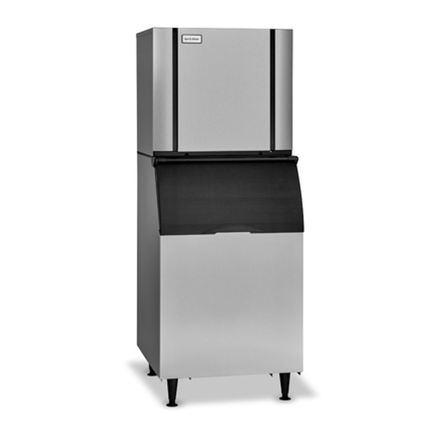
Ice-O-Matic CIM0320 Technical & Service Manual
Elevation series cube ice maker.
cim modular cubers
Hide thumbs
Also See for CIM0320:
- Technical & service manual (84 pages) ,
- Installation manual and owner's manual (22 pages) ,
- Installation manual and owner's manual (22 pages)

Related Manuals for Ice-O-Matic CIM0320


Summary of Contents for Ice-O-Matic CIM0320
- Page 1 ELEVATION SERIES CUBE ICE MAKER CIM Modular Cubers CIM0320 - CIM1136 Technical Service Manual Ice-O-Matic 11100 East 45th Avenue Denver, Colorado 80239 1/2018 1-800-423-3367...
- Page 2 ELEVATION SERIES CIM CUBERS TABLE OF CONTENTS INTRODUCTION …………………………………………………………………………………………………………………………….…… .…1 AIR AND W ATER COOLED UNIT INSTALLATION GUIDELINES ……………………………………………………………….….2 REM OTE UNIT INSTALLATION GUIDELINES ……………………………………………………………………… ………………..…..4 ELECTRICAL AND PLUM BING REQUIREM ENTS …………………………………………………………………… ………………..7 START‐UP PROCEDURES ………………………………………………………………………………………………………………… .….…9 SEQUENCE OF OPERATIONS ………………………………………………………………………………………………………… .….….10 CONTROL BOARD …………………………………………………………………………………………………………………………….…...
- Page 3 ELEVATION SERIES CIM CUBERS TABLE OF CONTENTS...
-
Page 4: Introduction
Ice-O-Matic Warranty Every Ice-O-Matic ice maker is backed by a warranty that provides both parts and labor coverage. To view the warranty details, register products, or check your warranty status visit the “Warranty and Water Filter... -
Page 5: Installation Guidelines
40°F (4.5°C) units should be 1/2 inch O.D. minimum. The drain Maximum incoming water temperature: line fittings on Ice-O-Matic bins are 3/4 FPT. The 100°F (38°C) bin drain should be a minimum of 3/4 inch O.D. Minimum incoming water pressure: Cold water drains should be insulated to prevent 20 psi (1.4 bar, 0.138MPa) -
Page 6: Clearance Requirements
Ice-O-Matic, refer to the manufacturers instructions for machine mounting. Ice-O-Matic will not be responsible for damage or injury that results from unexpected closing of the bin door as a result of the ice machine being too far... - Page 7 Note: the openings in the building or ceiling or wall, requirements must receive written authorization listed in the next step, are the minimum sizes from Ice-O-Matic. This includes multi-pass or rack recommended for passing the refrigerant lines through. system remote condensers.
- Page 8 75 to 100 ft. actual line set run. CIM Machine Model Number Remote Condenser Model Number CIM0520/530 VRC1001B/RCA1001 CIM0525/535 VRC1061B/RCA1061 CIM0636 VRC1061B/RCA1061 CIM1126 VRC1061B/RCA1061 CIM0835/0836/0837 VRC1061B/RCA1061 CIM1135/1136/1137 VRC1061B/RCA1061 Verify the CIM machine is compatible with the remote condenser. For more information contact your Ice-O-Matic distributor.
- Page 9 ELEVATION SERIES CIM CUBERS REMOTE CONDENSER GUIDELINES Equivalent Run Calculation Examples Formula for maximum equivalent run: (RISE X 1.7) + (DROP X 6.6) + HORIZONTAL RUN = CALCULATED LINE RUN NOT TO EXCEED 100 CALCULATED FEET Rise: (35 ft. x 1.7) + (40 ft.) = 99.5 equivalent feet line run 35 ft.
-
Page 10: Electrical And Plum Bing Requirem Ents
ELEVATION SERIES ELECTRICAL AND PLUMBING REQUIREMENTS Electrical and Plumbing Requirements 22” CIM SERIES Common Connections (CIM**2* A) Air Cooled Please note: air-cooled units require 6”(152mm) for air intake and exhaust. A. Ice maker potable water in, 3/8” FPT. B. Ice maker water out, 3/4”... -
Page 11: Electrical And Plumbing Requirements
ELEVATION SERIES ELECTRICAL AND PLUMBING REQUIREMENTS Electrical and Plumbing Requirements 30” CIM SERIES Common Connections (CIM**3* A) Air Cooled Please note: air-cooled units require 6”(152mm) for air intake and exhaust. A. Ice maker potable water in, 3/8” FPT. B. Ice maker water out, 3/4”... -
Page 12: Start‐Up Procedures
ELEVATION SERIES START-UP PROCEDURE Start-Up Procedure Note: Before starting the machine, make sure the machine is level within 1/8 inch in all directions, the bin or dispenser leg height can be adjusted by rotating the leg foot After verifying proper voltage, water supply, drains and breathable air space around the unit, press and quickly release the ON/OFF button behind the unit front panel. -
Page 13: Sequence Of Operations
ELEVATION SERIES CIM CUBERS SEQUENCE OF OPERATIONS SEQUENCE OF OPERATIONS BLUE w/ WHITE BLUE w/ RED 12V DC Switches WHITE WHITE BLUE R5 R6 Line Voltage BLUE BLACK YELLOW = Illuminated LED BROWN VIOLET PINK Components CONTROL BOARD - OFF STATUS When power is initially applied to the unit, the LED’s on both the Push Pad and the Board POWER Button will flash in sequence BLUE, then RED, then the WASH Button will flash YELLOW, followed by the POWER Button LED will turn a solid RED, indicating the unit is in the OFF status as shown above. - Page 14 ELEVATION SERIES CIM CUBERS SEQUENCE OF OPERATIONS BLUE w/ WHITE BLUE w/ RED 12V DC Switches WHITE WHITE BLUE R5 R6 Line Voltage BLUE BLACK YELLOW = Illuminated LED BROWN VIOLET PINK Components CONTROL BOARD - FREEZE CYCLE A quick press of the POWER button on the Push Pad or Board will start the Freeze cycle. The Water Inlet Valve will be energized (R4 LED on Board illuminated) and water will begin flowing into the Sump.
- Page 15 ELEVATION SERIES CIM CUBERS SEQUENCE OF OPERATIONS BLUE w/ WHITE BLUE w/ RED 12V DC Switches WHITE WHITE BLUE Line Voltage BLUE BLACK YELLOW = Illuminated LED BROWN VIOLET PINK Components CONTROL BOARD - COMPRESSOR START The Hot Gas Valve will be energized (R3 on Board illuminated) for 5 seconds and the system pressures will start to equalize.
- Page 16 ELEVATION SERIES CIM CUBERS SEQUENCE OF OPERATIONS BLUE w/ WHITE BLUE w/ RED 12V DC Switches WHITE WHITE BLUE Line Voltage BLUE BLACK YELLOW = Illuminated LED BROWN VIOLET PINK Components CONTROL BOARD - COMPRESSOR START The Compressor will be energized (R2 on Board illuminated) and the Hot Gas Valve will remain open for 5 more seconds and then de‐energize (R3 on Board off).
- Page 17 ELEVATION SERIES CIM CUBERS SEQUENCE OF OPERATIONS BLUE w/ WHITE BLUE w/ RED 12V DC Switches WHITE WHITE BLUE Line Voltage BLUE BLACK YELLOW = Illuminated LED BROWN VIOLET PINK Components CONTROL BOARD - PRE-CHILL The Compressor and Fan(s)/Liquid Line Solenoid (R1 and R2 LED’s on Board illuminated) are energized and unit is now in a Pre‐Chill for 30 seconds bringing the Evaporator temperature down.
- Page 18 ELEVATION SERIES CIM CUBERS SEQUENCE OF OPERATIONS BLUE w/ WHITE BLUE w/ RED 12V DC Switches WHITE WHITE BLUE Line Voltage BLUE BLACK YELLOW = Illuminated LED BROWN VIOLET PINK Components CONTROL BOARD - FREEZE The Water Pump is energized (R6 LED on Board illuminated) and water is pushed through the Water Pump Tube and flows over the Evaporator.
- Page 19 ELEVATION SERIES CIM CUBERS SEQUENCE OF OPERATIONS BLUE w/ WHITE BLUE w/ RED 12V DC Switches WHITE WHITE BLUE Line Voltage BLUE BLACK YELLOW = Illuminated LED BROWN VIOLET PINK Components CONTROL BOARD - ANTI-SLUSH During the first 3 cycles as the water temperature reaches 36 degrees F. the Water Pump will shut off for 20 seconds to reduce the possibility of slush developing in the Sump.
- Page 20 ELEVATION SERIES CIM CUBERS SEQUENCE OF OPERATIONS BLUE w/ WHITE BLUE w/ RED 12V DC Switches WHITE WHITE BLUE Line Voltage BLUE BLACK YELLOW = Illuminated LED BROWN VIOLET PINK Components CONTROL BOARD - WATER PUMP ON At the end of Anti‐Slush the Water Pump (R6) will be re‐energized and water starts flowing over the Evaporator again.
- Page 21 ELEVATION SERIES CIM CUBERS SEQUENCE OF OPERATIONS BLUE w/ WHITE BLUE w/ RED 12V DC Switches WHITE WHITE BLUE Line Voltage BLUE BLACK YELLOW = Illuminated LED BROWN VIOLET PINK Components CONTROL BOARD - INITIATING HARVEST When the water level in the SUMP drops to close the contacts of the Low Float Switch (LED on Board illu‐ minates) after a 5 second de‐bounce of the switch will signal the start of the Harvest Cycle.
- Page 22 ELEVATION SERIES CIM CUBERS SEQUENCE OF OPERATIONS BLUE w/ WHITE BLUE w/ RED 12V DC Switches WHITE WHITE BLUE Line Voltage BLUE BLACK YELLOW = Illuminated LED BROWN VIOLET PINK Components CONTROL BOARD - HARVEST After the contacts of the Low Float Switch close, the Harvest Cycle starts by energizing the Hot Gas Valve, Harvest Assist, Purge Valve AND Water Inlet Valve (R2, R3, R4, R5 and R6 are illuminated on Air and Water Cooled units, ALL Relays are energized on Remotes.) The Purge Valve will close after 7 seconds.
- Page 23 ELEVATION SERIES CIM CUBERS SEQUENCE OF OPERATIONS BLUE w/ WHITE BLUE w/ RED 12V DC Switches WHITE WHITE BLUE Line Voltage BLUE BLACK YELLOW = Illuminated LED BROWN VIOLET PINK Components CONTROL BOARD - HARVEST After the Purge Valve and Water Pump de‐energize, the Water Inlet Valve will remain open for 20 sec‐ onds, partially filling the SUMP in preparation for the next Freeze Cycle (R2, R3, and R4, are illuminated on Air and Water Cooled units, R1 is also energized on Remotes.) The Low Float Switch will go off as the water level rises.
- Page 24 ELEVATION SERIES CIM CUBERS SEQUENCE OF OPERATIONS BLUE w/ WHITE BLUE w/ RED 12V DC Switches WHITE WHITE BLUE Line Voltage BLUE BLACK YELLOW = Illuminated LED BROWN VIOLET PINK Components CONTROL BOARD - HARVEST After the Water Inlet Valve closes following the 20 second time out, the Hot Gas Valve and Harvest Assist will remain energized until the ice slab is harvested from the Evaporator.
- Page 25 ELEVATION SERIES CIM CUBERS SEQUENCE OF OPERATIONS BLUE w/ WHITE BLUE w/ RED 12V DC Switches WHITE WHITE BLUE Line Voltage BLUE BLACK YELLOW = Illuminated LED BROWN VIOLET PINK Components CONTROL BOARD - BIN FULL As the ice slab falls from the Evaporator, the Curtain(s) is pushed out, contacts of the Magnetic Curtain Switch(s) open as the ice slab falls.
- Page 26 ELEVATION SERIES CIM CUBERS SEQUENCE OF OPERATIONS BLUE w/ WHITE BLUE w/ RED 12V DC Switches WHITE WHITE BLUE Line Voltage BLUE BLACK YELLOW = Illuminated LED BROWN VIOLET PINK Components CONTROL BOARD - RETURN TO FREEZE As the ice slab falls from the Evaporator, the Curtain(s) is pushed out and the contacts of the Curtain Switch(s) open and close, terminating the Harvest Cycle.
-
Page 27: Control Board
ELEVATION SERIES CIM CUBER CONTROL BOARD Control Board Operation The Board controls the operation of the unit. A series of LED lights show Switch positions and Component operation to assist the tech‐ nician in understanding and troubleshooting issues that may arise. See Sequence of Opera‐ tion pg. - Page 28 ELEVATION SERIES CIM CUBER CONTROL BOARD Adjustment Switch Block Three adjustments can be made on the block. Extended Purge, Bin Thermostat Kit add-on and Cleaning Needed Reminder. Standard Purge time during a Defrost Cycle is set at 7 seconds. To add an additional 5 seconds to the purge time, move Switch 1 to the right, to the ON position.
- Page 29 ELEVATION SERIES CIM CUBER CONTROL BOARD Power and Clean LED Flash Description SOLID - On Constantly SLOW - Flashes once every second QUICK - Flashes once every half second DOUBLE SLOW - Flashes twice then 1 second delay DELAYED - flashes once every 3 seconds Error Codes Error 1 - POWER LED QUICK FLASH RED - Unit has experienced a MAX Freeze (1 hr), MAX Harvest (5.5 minutes) or BOTH.
- Page 30 ELEVATION SERIES CIM CUBERS BOARD COMPONENT LED SEQUENCE BOARD LED SEQUENCE DURING OPERATION ‐ INITIAL FREEZE CYCLE AT START‐UP...
- Page 31 ELEVATION SERIES CIM CUBERS BOARD COMPONENT LED SEQUENCE BOARD LED SEQUENCE DURING OPERATION ‐ INITIAL HARVEST CYCLE AT START‐UP...
- Page 32 ELEVATION SERIES CIM CUBERS BOARD COMPONENT LED SEQUENCE BOARD LED SEQUENCE DURING OPERATION ‐ TRANSITION FROM HARVEST TO FREEZE...
- Page 33 ELEVATION SERIES CIM CUBERS BOARD COMPONENT LED SEQUENCE BOARD LED SEQUENCE DURING OPERATION ‐ BIN FULL (CURTAIN OR STAT)
- Page 34 ELEVATION SERIES CIM CUBERS BOARD COMPONENT LED SEQUENCE BOARD LED SEQUENCE DURING OPERATION ‐ DIAGNOSTICS IN FREEZE CYCLE The Diagnostic sequence is started by pressing both the Power and Clean buttons for 6 seconds.
- Page 35 ELEVATION SERIES CIM CUBERS BOARD COMPONENT LED SEQUENCE BOARD LED SEQUENCE DURING OPERATION ‐ DIAGNOSTICS IN HARVEST CYCLE...
-
Page 36: Button Function
ELEVATION SERIES CIM CUBERS BUTTON FUNCTIONS... -
Page 37: Sump
ELEVATION SERIES CIM CUBER SUMP Sump The Sump holds the potable water for the Freeze Cycle.It is located under the Evaporator and accessible from the front of the unit. The Sump must be removed to access the Water Pump and the Float Switch Housing. Splash Guard Splash Curtain SUMP... - Page 38 ELEVATION SERIES CIM CUBER SUMP Sump Retainer Lift front of Sump and pull forward to clear the Sump Retainers from the frame. Support Tab With the Support Tabs now clear of the frame, allow the back of the Sump to fall clear of the frame.
-
Page 39: High And Low Float Sw Itches And Housing
ELEVATION SERIES CIM CUBER HIGH AND LOW FLOAT SWITCHES AND HOUSING Float Housing Assembly The Float Switch Housing Assembly contains the High and Low Float Switches along with the Sump Thermistor. See below for function of each. See also Sequence of Operation pg. 9. High Float Thermistor... - Page 40 ELEVATION SERIES CIM CUBER HIGH AND LOW FLOAT SWITCHES AND HOUSING the Sump during the Freeze Cycle. During the first 3 cycles following a full bin shut down or being turned on (initial start‐up), the unit will perform an “Anti‐slush” shutdown of the Water Pump for 20 seconds when the water temperature reaches 36 degrees F to reduce the possibility of the water in the Sump slushing.
- Page 41 ELEVATION SERIES CIM CUBER HIGH AND LOW FLOAT SWITCHES AND HOUSING Thicker Splash Curtain Bridge Thinner Sump Bridge The Bridge Thickness on units under 400# production should be 3/16” while units over 400# pro‐ duction should be 1/8” thick when measured across the middle of the plate. Minor Adjustments can be made to the bridge thickness by moving the Water Level Adjustment Arm of the Float Housing up for a thinner bridge or down for a thicker bridge.
-
Page 42: Water Pump
ELEVATION SERIES CIM CUBER WATER PUMP Water Pump Operation Relay 6 on the Board (LED ON) energizes the Water Pump after the 30 second Pre‐Chill of the Evaporator during the Freeze Cycle. In the first 3 Freeze Cycles after a shutdown (turned OFF or Bin Full) the Water Pump will perform a shutdown for 20 seconds to help prevent the Sump from slushing. - Page 43 ELEVATION SERIES CIM CUBER WATER PUMP Water Pump Removal The “foot” of the Water Pump points towards the right front corner of the unit. Grasp the foot and turn counter clockwise. When the foot points towards the right rear corner, you will feel the weight of the pump as the collar clears the base connections.
-
Page 44: W Ater Distribution Tube
ELEVATION SERIES CIM CUBER WATER DISTRIBUTION TUBE Water Distribution Tube The Water Distribution Tube has an inner tube and an outer tube. The water enters through the inner tube and sprays the water up into the outer tube relieving the pressure on the water. - Page 45 ELEVATION SERIES CIM CUBER WATER DISTRIBUTION TUBE The Water Distribution Tube comes apart easily. It should be taken apart and cleaned regularly along with the rest of the unit. The pieces are Pokeyoke, meaning it only goes back together one way.
-
Page 46: W Ater Inlet Valve
ELEVATION SERIES CIM CUBER WATER INLET VALVE Water Inlet Valve Operation Relay 4 on the Board (LED ON) energizes the Valve first on initial start‐up to fill the Sump until the contacts of the High Float Switch open, indicating a proper amount of water for ice making. -
Page 47: Purge Valve
ELEVATION SERIES CIM CUBER PURGE VALVE Purge Valve Operation The Purge Valve is located in the back of the Evaporator. The Valve should open when energized by Relay 5 on the Board (LED ON) during the Harvest Cycle to help empty the mineral laden water (see Sequence of Opera‐... -
Page 48: Harvest Assist Assem Bly / Hot Gas Valve
ELEVATION SERIES CIM CUBER HARVEST ASSIST ASSEMBLY/HOT GAS VALVE Harvest Assist Assembly/Hot Gas Valve Operation The Harvest Assist Assembly is mounted to the back of the Evaporator Assembly. It is energized by Relay 3 along with the Hot Gas Valve. As the unit enters the Harvest Cycle, Relay 3 will illuminate indicating voltage is being sent to the Harvest Assist Assembly and the probe will be pushed forward to meet the... -
Page 49: Evaporator
ELEVATION SERIES CIM CUBER EVAPORATOR Evaporator Assembly The nickel plated Evaporator Assembly has a copper core to assure good heat transfer. Water is pumped gently over the Evaporator during the freeze cycle for even ice formation. Evaporator Operation The Evaporator should be fully flooded with refrigerant for most of the freeze cycle to assure even ice formation. - Page 50 ELEVATION SERIES CIM CUBERS EVAPORATOR REPLACEMENT While recovering the refrigerant from the unit, disconnect High and Low Float Switches, Thermistor, Curtain Switch and Push Pad ribbon and move the wiring clear of the area. Connectors Evaporator Top Remove the Splash Curtain, Evaporator Cover, Top Evaporator Cover, Water Distribution Tube, Evaporator Cover Water Pump Tube and its connector, Sump, Water...
- Page 51 ELEVATION SERIES CIM CUBERS EVAPORATOR REPLACEMENT...
- Page 52 ELEVATION SERIES CIM CUBERS EVAPORATOR REPLACEMENT Surround Pull bottom of frame out to clear left hand surround. Grasp and remove Evaporator freeing the Left Hand side first. The Left Hand Surround will come out with the Evaporator; the Right Hand surround will be left in place.
-
Page 53: M Agnetic Curtain Sw Itch
ELEVATION SERIES CIM CUBER MAGNETIC CURTAIN SWITCH Magnetic Curtain Switch The Magnetic Curtain Switch is a proximity switch that closes the contacts when the Splash Curtain closes. LED’s on the Board indi‐ cate a closed switch when illuminated. Magnet Connector Troubleshooting Should the LED’s on the Board be off when the Splash Curtain is closed, first verify the magnet is in place on the Splash Curtain and the Wiring Harness is properly connected at the Switch and at... - Page 54 ELEVATION SERIES CIM CUBER HIGH PRESS CUT‐OUT AND FAN CYCLE SWITCH High Pressure Cut-out (left) The High Pressure Cut‐out is set to open at 450 psig and de‐energizes the Contactor as a safety on the unit. Fan Cycle Control (right) The Fan Cycle Control helps maintain head pressure in cooler ambient temps.
- Page 55 ELEVATION SERIES CIM CUBER HIGH TEMP SAFETY High Temp Safety The High Temp Safety is a bi‐metal thermostat strapped to the line at the outlet of the Hot Gas Valve. Should the Hot Gas Valve stick open and the refrigerant line reach 180 degrees F., the High Temp Safety would open, dropping power to the Contactor and shut down the Compressor.
-
Page 56: Fan Motor
ELEVATION SERIES CIM CUBER FAN MOTOR Fan Motor Operation The Fan Motor (Self Contained Air Cooled Units) is Mounted to the Fan Shroud covering the Condenser at the rear of the unit. It is energized by Relay 1 and controlled by the Fan Cycling Switch. -
Page 57: Refrigeration Section
ELEVATION SERIES CIM CUBER REFRIGERATION SECTION REFRIGERATION SECTION The Refrigeration Section on a CIM Cuber con‐ tains the Compressor, Thermostatic Expan‐ sion Valve, Hot Gas Valve and Condenser. Remote systems also utilize a Mixing Valve (LAC), Liquid Line Solenoid and Receiver. Refrigeration Section Operation The Compressor drives the refrigeration system. - Page 58 ELEVATION SERIES CIM CUBER REFRIGERATION SECTION Hot Gas Valve The Hot Gas Solenoid Valve opens to provide gas to the Evaporator during the Harvest Cycle. Troubleshooting - Hot Gas Valve Should the valve not open at the initiation of the Harvest Cycle (R3 LED ON), verify voltage at the coil of the solenoid.
-
Page 59: General M Aintenance
ELEVATION SERIES CIM CUBERS GENERAL MAINTENANCE Electrical shock and/or injury from moving parts inside this machine can cause serious injury. Disconnect electrical supply to machine prior to performing any adjustments or repairs. Failure to perform the required maintenance at the frequency specified will void warranty coverage in the event of a related failure. - Page 60 Descaling should be scheduled at a minimum of twice per year but no more than once per month. Descaling dissolves the mineral deposits on the evaporator and other surfaces. It removes scale, calcium, lime scale and other mineral buildup. Ice-O-Matic requires a “nickel-safe” cleaner such as Nu-Calgon Nickel-Safe Ice Machine Cleaner or equivalent diluted per manufacturer’s instructions.
- Page 61 1.6 fl. oz. per 1 gal. of water 5 fl.oz. per 1 gal. of water (12.5 mL per 1 Liter of water) (39 mL per 1 Liter of water) CIM0320/330 .9 (3.4) Add 4.5 fl. oz. (133 mL) Add 1.5 fl. oz. (44mL) CIM0430/520/530/630 1.2 (4.5)
-
Page 62: Cabinet Care
ELEVATION SERIES CIM CUBERS CABINET CARE Chemicals for Descaling and Sanitizing It is important to use solutions that do not harm the ice machine. Never use cleaning or sanitizing solutions that contain Nitric Acid, Sulfuric Acid, Hydrochloric Acid, Carbolic Acid, Acetic Acid, diluted Acetic Acid or non- food-grade vinegar (concentration of acetic acid greater that 6% and does not contain enzymes created in processing) or any chlorine-based solution such as bleach, chlorine dioxide or any type of salts such as potassium chloride (potassium salts) or sodium chloride. -
Page 63: W Interizing
ELEVATION SERIES CIM CUBERS WINTERIZING PROCEDURES Winterizing Procedures IMPORTANT: Whenever the ice machine is taken out of operation during the winter months, the procedure below must be performed. Failure to do so may cause serious damage and will void all warranties. 1. -
Page 64: Technical Specifications
ELEVATION SERIES CIM CUBERS TECHNICAL SPECIFICATIONS Avg. Batch Approx Cycle Voltage/Hz/P Approx. Approx. Head Avg. Water Usage per 100 Min Circuit Max Fuse Charge in Model Weight Time 90/70 in kWH Used Comp. LRA Comp. RLA Ref. Type hase Suction Press Press lbs. -
Page 65: W Iring Diagram S
ELEVATION SERIES WIRING DIAGRAM CIM0320, 0330, 0430, 0436, 0520, 0530, 0636, 0836, and 1136 AIR AND WATER COOLED UNITS... - Page 66 ELEVATION SERIES WIRING DIAGRAM CIM0325, 0335, 0435, 0525, 0535, 0635, 0835 and 1135 AIR AND WATER COOLED UNITS...
- Page 67 ELEVATION SERIES WIRING DIAGRAM CIM0530, 0636, 0836 1126 and 1136 REMOTE COOLED UNITS...
- Page 68 ELEVATION SERIES WIRING DIAGRAM CIM0535, 0835, and 1135 REMOTE COOLED UNITS...
Need help?
Do you have a question about the CIM0320 and is the answer not in the manual?
Questions and answers