Table of Contents
Advertisement
Quick Links
Advertisement
Table of Contents

Related Manuals for Vertiv Liebert STS2/PDU


Summary of Contents for Vertiv Liebert STS2/PDU
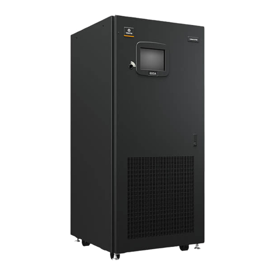
- Page 1 Liebert STS2 ® ™ User Manual—100-1000A, 50/60Hz...
- Page 3 Seismic Floor Anchors ................16 Vertiv | Liebert ®...
- Page 4 Alarm Notes ..................70 Vertiv | Liebert ®...
- Page 5 Key Lockout Switch ................101 Vertiv | Liebert ®...
- Page 6 APPENDIX B - PROGRAMMABLE RELAY BOARD SETTINGS RECORD....A132 APPENDIX C - INPUT CONTACT ISOLATOR SETTINGS RECORD ....A134 Vertiv | Liebert ®...
- Page 7 Figure 39 Installation drawing, seismic floor stand 800-1000A ......... . 52 Vertiv | Liebert ®...
- Page 8 Torque tightening ................130 Vertiv | Liebert ®...
-
Page 9: Important Safety Instructions
Read the entire manual before installing or operating the system. Adhere to all operating instructions and warnings on the unit and in this manual. Vertiv neither recommends nor knowingly sells this product for use with life support or other FDA-designated “critical” devices. -
Page 10: Overview Of Manual
16.0 - Event Message Help Text—provides the help text for the various system event messages. This help is also available through the touchscreen interface. 17.0 - Maintenance—briefly discusses routine maintenance, provides proper torque settings for nuts and bolts, and provides the Vertiv contact information for technical support. Vertiv | Liebert ®... -
Page 11: Safety Precautions
A Note emphasizes important text. If the instructions are not properly followed, the equipment could be damaged or may not properly operate. For example: NOTE Read this entire manual before installing and operating the unit. Vertiv | Liebert ® ™... -
Page 12: Unpacking And Inspections
Locate the bag containing the keys for the front access door. The bag is attached to the cabinet. Compare the contents of the shipment with the bill of lading. Report any missing items to the carrier and to Vertiv Services immediately. -
Page 13: Handling Considerations
Check for any unsafe condition that may be a potential safety hazard. After the Liebert STS2 has been inspected and no problems are found, the unit can be moved to its installation location. If using a forklift, remember to lift the unit from the rear. Vertiv | Liebert ®... -
Page 14: Location Considerations
Above 4000 ft. (1200m), output current is derated by 6% per 1000 ft. (18% per 1000m). • Storage/Transport Altitude: Up to 40,000 ft. (12,200m) above sea level. • Audible Noise: Less than 55 dBA at 5 ft. (1.5m) with audible alarm Off. Vertiv | Liebert ®... -
Page 15: Altitude
100.4 (38) 98.6 (37) 96.8 (36) 95.0 (35) 93.2 (34) 91.4 (33) 89.6 (32) 87.8 (31) 86.0 (30) Altitude, Feet (M) Above Sea Level Vertiv | Liebert ® ™ STS2 100-1000A, 50/60Hz User Manual | Rev. 12 | 11/2017 ™... -
Page 16: Locating The Liebert Sts2
Liebert STS2 to the floor stand and to the concrete floor. The seismic floor stand is shipped separately from the unit when ordered. See Figures 29 through 40 for instructions and details for installing seismic floor stand. Vertiv | Liebert ®... -
Page 17: Power And Control Wiring
For 4-wire operation, the common source neutral must be connected to the Liebert STS2. See Figure 2 on page 10 for a typical one-line diagram. Refer to Figures 13 to 18 for electrical field connections on all units, with both single and dual output breakers. Vertiv | Liebert ®... -
Page 18: System Grounding
If conduit is used as a grounding means, adequate electrical continuity must be maintained at all conduit connections. The use of isolating bushings with a metal conduit can be a safety hazard and is not recommended. Vertiv | Liebert ®... -
Page 19: Figure 3 Typical One-Line Diagram Of Two Pdus And A Liebert Sts2
Source 1 Source 2 MICB1 MICB2 Isolation Isolation Transformer Transformer STS1 STS2 K2 K3 K1 K3 225 A 225A 225 A 225A 225A 225A Vertiv | Liebert ® ™ STS2 100-1000A, 50/60Hz User Manual | Rev. 12 | 11/2017 ™... -
Page 20: Control Wiring Connections
200V to 600V. The unit is set at the factory to match the nameplate voltage. Field adjustments are not necessary. If the unit needs to operate at a voltage other than what is listed on the nameplate, contact Vertiv Services or your local Vertiv representative. -
Page 21: Options
See Configuring the Input Contact Isolator Settings on page 91 for instructions on configuring the connections. See Figures 19 and 20 for the location of the ICI. See Figure 23 for wiring details. Vertiv | Liebert ®... -
Page 22: Comms Board
LED’s and buttons. LED’s alert you when a problem occurs. A PC running terminal emulation software connected to the RS-232 port is needed to access the data and configuration settings. Vertiv | Liebert ®... -
Page 23: Remote Source Selection Wiring
Liebert STS2 will not transfer and remain on its present source even if the source is no longer supplying power. This option requires an Input Contact Isolator board (see 6.4 - Input Contact Isolator Board). Vertiv | Liebert ®... -
Page 24: Input Junction Box Installation—Optional
Liebert STS2. The stands can be fastened to the floor to meet seismic Zone 4 requirements. See 4.0 - Locating the Liebert STS2 and Figures 29 through 40 for instructions and details for installing seismic floor stands. Vertiv | Liebert ®... -
Page 25: Installation Drawings
Mounting bolts must be threaded into PS211100 the unit from underneath the unit base. If a floor stand is used, Rev. 6 the casters must rest on the floor stand to support the unit's weight. Vertiv | Liebert ® ™ STS2 100-1000A, 50/60Hz User Manual | Rev. -
Page 26: Figure 5 Outline Drawing: 400 – 600 Amp Liebert Sts2
Mounting bolts must be threaded into Rev. 4 the unit from underneath the unit base. If a floor stand is used, the casters must rest on the floor stand to support the unit's weight. Vertiv | Liebert ® ™... -
Page 27: Figure 6 Outline Drawing: 800 – 1000 Amp Liebert Sts2
If a floor stand is used, the casters must rest on the floor stand to support PS211800 the unit's weight. Rev. 4 10. 500 CFM (236 L/S) per exhaust fan. Vertiv | Liebert ® ™ STS2 100-1000A, 50/60Hz User Manual | Rev. 12 | 11/2017... -
Page 28: Figure 7 Outline Drawing: 100 – 250Amp Liebert Sts2 With A Key Lockout Switch Option
Mounting bolts must be threaded into the unit from underneath the unit base. If a floor stand is used, PS211101 the casters must rest on the floor stand to support the unit's weight. Rev. 5 Vertiv | Liebert ® ™ STS2 100-1000A, 50/60Hz User Manual | Rev. -
Page 29: Figure 8 Outline Drawing: 400 – 600 Amp Liebert Sts2 With A Key Lockout Switch Option
PS211401 the unit mounting holes from underneath the unit base. If a floor stand is used, the casters must rest on the floor stand to support Rev. 4 the unit's weight. Vertiv | Liebert ® ™ STS2 100-1000A, 50/60Hz User Manual | Rev. 12 | 11/2017... -
Page 30: Figure 9 Outline Drawing: 800 – 1000 Amp Liebert Sts2 With The Key Lockout Switch Option
If a floor stand is used, the casters must PS211801 rest on the floor stand to support the unit's weight. Rev. 4 10. 500 CFM (236 L/S) per exhaust fan. Vertiv | Liebert ® ™ STS2 100-1000A, 50/60Hz User Manual | Rev. 12 | 11/2017... -
Page 31: Figure 10 Seismic Anchor Drawing: 100 – 250 Amp Liebert Sts2
1010 steel and approximately 1/4" 365 lb./in. (41.2Nm). Loosen leveling bolt locking nut and (6.4mm) thick. tighten after the bracket is secured. PS211105 Rev. 1 Vertiv | Liebert ® ™ STS2 100-1000A, 50/60Hz User Manual | Rev. 12 | 11/2017... -
Page 32: Figure 11 Seismic Anchor Drawing: 400 – 600 Amp Liebert Sts2
7. If side walls are present, 5" (127mm) minimum distance from either side Rev. 1 wall is required. 8. Rear and front floor brackets and the rear and front cabinet base brackets are 1010 steel and approximately 1/4" (6.4mm) thick. Vertiv | Liebert ® ™ STS2 100-1000A, 50/60Hz User Manual | Rev. -
Page 33: Figure 12 Seismic Anchor Drawing: 800 – 1000 Amp Liebert Sts2
1010 steel and approximately 1/4" 365 lb./in. (41.2Nm). Loosen leveling bolt locking nut and (6.4mm) thick. tighten after the bracket is secured. PS211805 Rev. 1 Vertiv | Liebert ® ™ STS2 100-1000A, 50/60Hz User Manual | Rev. 12 | 11/2017... -
Page 34: Breaker
PS212100 6. The torque requirement for 1/2" - 13 PEM nuts is Rev. 4 428 in./lb (48Nm). Vertiv | Liebert ® ™ STS2 100-1000A, 50/60Hz User Manual | Rev. 12 | 11/2017... -
Page 35: Breakers
Kit includes 1/2" bolts, washers and nuts for connecting PS212101 cables to the busbars. Rev. 5 6. The torque requirement for 1/2" - 13 PEM nuts is 428 in./lb (48Nm). Vertiv | Liebert ® ™ STS2 100-1000A, 50/60Hz User Manual | Rev. 12 | 11/2017... -
Page 36: Breaker
Kit includes 1/2" bolts, washers and nuts for connecting PS212400 cables to the busbars. 6. The torque requirement for 1/2" - 13 PEM nuts is 428 in./lb (48Nm). Rev. 4 Vertiv | Liebert ® ™ STS2 100-1000A, 50/60Hz User Manual | Rev. 12 | 11/2017... -
Page 37: Breakers
1/2" bolts, washers and nuts for connecting cables to the busbars. 6. The torque requirement for 1/2" - 13 PEM nuts PS212401 is 428 in./lb (48Nm). Rev. 4 Vertiv | Liebert ® ™ STS2 100-1000A, 50/60Hz User Manual | Rev. 12 | 11/2017... -
Page 38: Breaker
PS212800 System Output 6. The torque requirement for 1/2" - 13 PEM nuts is 428 in./lb (48Nm). Rev. 6 ONE-LINE DIAGRAM Vertiv | Liebert ® ™ STS2 100-1000A, 50/60Hz User Manual | Rev. 12 | 11/2017... -
Page 39: Figure 18 Electrical Field Connections: 800 – 1000 Amp Liebert Sts2 With Dual Output Breakers
PS212801 System Output 6. The torque requirement for 1/2" - 13 PEM nuts is 428 in./lb (48Nm). ONE-LINE DIAGRAM Rev. 7 Vertiv | Liebert ® ™ STS2 100-1000A, 50/60Hz User Manual | Rev. 12 | 11/2017... -
Page 40: Figure 19 Control Connection Location Diagram: 100 – 600 Amp Liebert Sts2
Board (Option); See Note 2 Network Interface Card (Option) Comms Board for Liebert CONTROL WIRING OPTION LOCATION DETAIL SiteScan PS213000 Front; Door Not Shown Rev. 2 Vertiv | Liebert ® ™ STS2 100-1000A, 50/60Hz User Manual | Rev. 12 | 11/2017 ™... -
Page 41: Figure 20 Control Connection Location Diagram: 800 – 1000 Amp Liebert Sts2
Board (Option); See Note 2 Detail Network Interface Card (Option) Comms Board for Liebert SiteScan OPTION PS213800 CONTROL WIRING LOCATION DETAIL Rev. 2 Front; Door Not Shown Vertiv | Liebert ® ™ STS2 100-1000A, 50/60Hz User Manual | Rev. 12 | 11/2017 ™... -
Page 42: Figure 21 Control Wiring For Remote Source Selection Option
4. Refer to Static Transfer Switch control connection diagram for location PS213007 of remote source selection option. All wiring must be in accordance Rev. 2 with national and local electrical codes. Vertiv | Liebert ® ™ STS2 100-1000A, 50/60Hz User Manual | Rev. 12 | 11/2017... -
Page 43: Figure 22 Control Wiring For The Programmable Relay Board Option
1 - 3 4 - 6 7 - 9 10 - 12 1 - 3 4 - 6 7 - 9 10 - 12 Vertiv | Liebert ® ™ STS2 100-1000A, 50/60Hz User Manual | Rev. 12 | 11/2017 ™... -
Page 44: Figure 23 Control Wiring For The Input Contact Isolator Board Option
Input Contact 8 (Pins 15 and 16). When the customer contact closes, transfers will be inhibited as long as the contact remains closed. Input Contact 8 is factory-set so no setup is required. The Transfer Inhibit option prevents Input Contact 8 from being used for any other input. Vertiv | Liebert ®... -
Page 45: Figure 24 Control Wiring For Comms Board
Comms Board. 4. All wiring must be in accordance with national PS213003 and local electrical codes. Rev. 4 Vertiv | Liebert ® ™ STS2 100-1000A, 50/60Hz User Manual | Rev. 12 | 11/2017... -
Page 46: Figure 25 Control Wiring For The Liebert Intellislot Snmp/Web/Modbus 485 Card
5. Refer to control connection location diagram of static transfer switch for location of Liebert IntelliSlot Web/485 card option. PS213008 6. All wiring must be in accordance with national and local electrical codes. Rev. 3 Vertiv | Liebert ® ™ STS2 100-1000A, 50/60Hz User Manual | Rev. -
Page 47: Figure 26 Control Wiring For The Rs-232 Port
6 7 8 9 1 2 3 4 5 DB9 Connector Detail A Front View PS213006 Upper Half of Unit Rev. 1 With Door Open Vertiv | Liebert ® ™ STS2 100-1000A, 50/60Hz User Manual | Rev. 12 | 11/2017 ™... -
Page 48: Figure 27 Outline Drawing For Input Junction Box
(2) #6 AWG to (2) 250A - 600A 16 (406) 30 (762) 6 (152) 33 (830) 10 (254) 32 (813) 7/16 (11) 3 (76) 500 kcmil Vertiv | Liebert ® ™ STS2 100-1000A, 50/60Hz User Manual | Rev. 12 | 11/2017 ™... -
Page 49: Figure 28 Led Display
Alarm Reset Push Button Alarm Present PS211002 Green CB1 Closed Rev. N Green CB2 Closed Green CB3 Closed Green CB3A Closed Yellow CB4 Closed Yellow CB5 Closed Vertiv | Liebert ® ™ STS2 100-1000A, 50/60Hz User Manual | Rev. 12 | 11/2017 ™... -
Page 50: Figure 29 Installation Drawing, Seismic Floor Stand 100-250A
M12-1.75x40mm cap screw, split lock washer and flat washer. Torque to 53 ft./lb. 523403G1 30.0" 31.25" 28.00" PS215000 523404G1 36.0" 37.25" 34.00" Rev. 3 Vertiv | Liebert ® ™ STS2 100-1000A, 50/60Hz User Manual | Rev. 12 | 11/2017 ™... -
Page 51: Figure 30 Installation Drawing, Seismic Floor Stand 100-250A
Lower Rear Mounting Bracket FIGURE 3 Front PS215001 See Drawings PS215000, PS215002 and PS215003 Top of Floor Stand Rev. 1 for details. with Lower Rear Mounting Bracket Vertiv | Liebert ® ™ STS2 100-1000A, 50/60Hz User Manual | Rev. 12 | 11/2017 ™... -
Page 52: Figure 31 Installation Drawing, Seismic Floor Stand 100-250A
M10 Flat Washer FIGURE 3 Lower Front Right Side View DETAIL A Bracket PS215002 2 Places See Drawings PS215000, PS215001 and PS215003 Rev. 1 for details. Vertiv | Liebert ® ™ STS2 100-1000A, 50/60Hz User Manual | Rev. 12 | 11/2017 ™... -
Page 53: Figure 32 Installation Drawing, Seismic Floor Stand 100-250A
30" (762mm) 32.1" (815mm) 77" (1956mm) Raised Floor FRONT VIEW SIDE RIGHT See Drawings PS215000, PS215001 and PS215002 for details. PS215003 Rev. 1 ISOMETRIC VIEW Vertiv | Liebert ® ™ STS2 100-1000A, 50/60Hz User Manual | Rev. 12 | 11/2017 ™... -
Page 54: Figure 33 Installation Drawing, Seismic Floor Stand 400-600A
M12-1.75x40mm cap screw, split lock washer and flat washer. Torque to 53 ft./lb. 523406G1 24.0" 25.25" 22.75" PS216000 523407G1 30.0" 31.25" 28.75" Rev.2 523408G1 36.0" 37.25" 374.75" 528737G2 14.0" 15.25" 12.75" 528737G1 12.0" 13.25" 10.75" Vertiv | Liebert ® ™ STS2 100-1000A, 50/60Hz User Manual | Rev. 12 | 11/2017 ™... -
Page 55: Figure 34 Installation Drawing, Seismic Floor Stand 400-600A
Lower Rear Mounting Bracket FIGURE 4 PS216001 Front Top of Floor Stand See Drawings PS216000, PS216002 and PS216003 Rev. 1 with Lower Rear Mounting Bracket for details. Vertiv | Liebert ® ™ STS2 100-1000A, 50/60Hz User Manual | Rev. 12 | 11/2017 ™... -
Page 56: Figure 35 Installation Drawing, Seismic Floor Stand 400-600A
M10 Flat Washer See Drawings PS216000, PS216001 and PS216003 for details. Lower Front Bracket FIGURE 3 PS216002 Right Side View DETAIL A Rev. 1 2 Places Vertiv | Liebert ® ™ STS2 100-1000A, 50/60Hz User Manual | Rev. 12 | 11/2017 ™... -
Page 57: Figure 36 Installation Drawing, Seismic Floor Stand 400-600A
38" 32.1" (965.2mm) (815mm) 77" (1956mm) Raised Floor RIGHT SIDE FRONT See Drawings PS216000, PS216001 and PS216002 for details. ISOMETRIC VIEW PS216003 Rev. 1 Vertiv | Liebert ® ™ STS2 100-1000A, 50/60Hz User Manual | Rev. 12 | 11/2017 ™... -
Page 58: Figure 37 Installation Drawing, Seismic Floor Stand 800-1000A
Liebert STS2 using M10-1.50x30mm cap screw, split lock washer and flat washer. Torque to 31 ft./lb. Attach the bracket to the floor stand using M12-1.75x40mm cap screw, split lock washer and flat washer. Torque to 53 ft./lb. Vertiv | Liebert ®... -
Page 59: Figure 38 Installation Drawing, Seismic Floor Stand 800-1000A
Right Side of Floor Stand Front Top of Floor Stand with Lower Rear Mounting Bracket with Lower Rear Mounting Bracket Leveling PS217001 Foot Rev. 2 DETAIL C Vertiv | Liebert ® ™ STS2 100-1000A, 50/60Hz User Manual | Rev. 12 | 11/2017 ™... -
Page 60: Figure 39 Installation Drawing, Seismic Floor Stand 800-1000A
M10 Flat Washer FIGURE 3 Right Side Lower Front PS217002 See Drawings PS217000, PS217001 Bracket Rev. 1 DETAIL A and PS217003 for details. 4 Places Vertiv | Liebert ® ™ STS2 100-1000A, 50/60Hz User Manual | Rev. 12 | 11/2017 ™... -
Page 61: Figure 40 Installation Drawing, Seismic Floor Stand 800-1000A
32" (813mm) 52" (1321mm) (815mm) 77" (1956mm) Raised Floor RIGHT SIDE FRONT See Drawings PS217000, PS217001 and PS217002 for details. ISOMETRIC VIEW PS217003 Rev. 1 Vertiv | Liebert ® ™ STS2 100-1000A, 50/60Hz User Manual | Rev. 12 | 11/2017 ™... -
Page 62: Introduction To Liebert Sts2 Operations
Information on the monitoring parameters would be available through the remote communication options, if available, or the DB9 (RS-232) connector located next to the LCD display behind the front door. See Figure 26 on page 39 for details. Vertiv | Liebert ®... -
Page 63: Reliability And Agency Requirements
8.1.3 Factory Backup and Service Assistance Because improper installation can cause a system to fail, a Vertiv Services service technician should thoroughly inspect the unit to ensure it is properly installed and its operating parameters are properly configured. Once the Liebert STS2 is properly installed, you, as the on-site operator, can easily monitor the unit’s operation utilizing the touchscreen or LED’s. -
Page 64: Bypass
Both units can be accessed from a terminal, or a PC running terminal emulation software, that is attached to the unit. Through the RS-232 access, you can monitor and configure the unit, plus remotely select a preferred source. See 12.1 - Using the RS-232 Port on page 73 for instructions on using the RS-232 interface. Vertiv | Liebert ®... -
Page 65: Theory Of Operation
You can enable and disable automatic retransfer to the preferred source through a user configuration setting. Vertiv | Liebert ®... -
Page 66: Emergency Transfer
On automatically. The touchscreen display (if so equipped) is active as long as at least one input source is energized and the Control Power Disconnect (located inside the static switch) is On. Vertiv | Liebert ®... -
Page 67: Detailed Component Description
CLOSED position. The switch trips OPEN before it disconnects from the plug-in base. See 15.2.5 - Circuit Breakers for specifications and more information pertaining to the circuit breakers. See Figure 13 to Figure 18 for circuit breaker locations. See submittal PS214002 for the circuit breaker schedule . Vertiv | Liebert ®... -
Page 68: Scr's
An RS-232 serial port is provided to allow an external terminal to be connected as another user interface. See 12.1 - Using the RS-232 Port on page 73 for more information on using the RS-232 port. Vertiv | Liebert ®... -
Page 69: Operating Instructions For The Touchscreen Interface
Before the unit is placed into service for the first time, after equipment relocation, or after the equipment has been de-energized for an extended period of time, a thorough equipment inspection and supervised startup by qualified personnel are strongly recommended. Contact your local Vertiv representative or Vertiv Services at 800-543-2378 to arrange for equipment inspection and startup. -
Page 70: Normal System Startup
Maintenance Bypass on page 64 for bypass instructions. If your system contains the LED front panel instead of the LCD touchscreen, refer to 14.2.2 - Manual Transfer / Preferred Source Selection for instructions on this procedure. Vertiv | Liebert ®... -
Page 71: Figure 42 Source Transfer Screen
If the Transfer Inhibit message is displayed, check for alarm messages on the Active Status window. Correct alarm conditions before attempting a source transfer. NOTE The preferred source may also be changed via the optional Remote Source Selection option, thereby initiating a transfer remotely. Vertiv | Liebert ® ™ STS2 100-1000A, 50/60Hz User Manual | Rev. -
Page 72: Enabling Remote Source Selection
Color Graphical Display is not available, open the front door and look through the slots in the control door. If you can see green LED’s on the gate driver board through that slot, then the unit is connected to the source referenced on the label below that slot. See Figure 43. Vertiv | Liebert ®... -
Page 73: Figure 43 Gate Board Viewing Slot Locations
If the Color Graphical Display is not available, you can still use the following bypass procedures, ignore the steps to check the display and check the LED’s. If your system contains the LED display, see 14.2.3 - Maintenance Bypass. Vertiv | Liebert ®... -
Page 74: Bypass Procedures For Source 1
14. Verify the STS SOURCE 2 box and CB2 breaker status on the Mimic screen. • If the Color Graphical Display is not available, check the gate driver board LED’s through the slots in the control panel. See Figure 43. Vertiv | Liebert ® ™... -
Page 75: Bypass Procedures For Source 2
Turn Off the load equipment per manufacturer’s recommendations. Open the bypass switch (CB4 or CB5) to turn Off the static transfer switch output. To completely de-energize the unit, turn OFF the power to both inputs to the Liebert STS2. Vertiv | Liebert ®... -
Page 76: Alarm And Faults
The logs can be accessed from the touchscreen menu or the RS-232 port. See 13.11 - Logs for more instructions on viewing the logs from the touchscreen. See Table 6 - Terminal commands on page 74 for the RS-232 interface commands used to access the logs. Vertiv | Liebert ®... -
Page 77: Event Log
• Critical Event — The event which triggered this log to be written. The event is indicated in red on the bar graph. • Frame Number — the current frame in the replay. A negative number indicates the replay is at a point before the triggering event occurred. Vertiv | Liebert ®... -
Page 78: Alarm Notes
PC terminal. An LED is used to indicate the presence of any active fault or alarm. Refer to 14.0 - Operating the Liebert STS2 LED Display for more information about the LED’s. Vertiv | Liebert ®... -
Page 79: Table 5 Event Messages
S2 I-PEAK I-PK on Source 2. A, F, E SOURCES OUT OF SYNC Source 1 and Source 2 are out of synchronization. A, E Vertiv | Liebert ® ™ STS2 100-1000A, 50/60Hz User Manual | Rev. 12 | 11/2017 ™... - Page 80 A, E Both History Logs have been written and no more history logs can be HIST LOGS FULL A, E written without clearing one of the logs. Vertiv | Liebert ® ™ STS2 100-1000A, 50/60Hz User Manual | Rev. 12 | 11/2017...
-
Page 81: Communication Interfaces
Communications options are also discussed in 6.0 - Options. 12.1 Using the RS-232 Port The RS-232 port is configured with a baud rate of 9600 with 8 data bits, 1 stop bit, no parity, and no hardware handshaking. Vertiv | Liebert ® ™ STS2 100-1000A, 50/60Hz User Manual | Rev. -
Page 82: Connecting And Using A Terminal
Displays status reports TIME? Displays current system time TIME Sets system time UPMDR? Displays metering data VER? Displays firmware versions Vertiv | Liebert ® ™ STS2 100-1000A, 50/60Hz User Manual | Rev. 12 | 11/2017 ™... -
Page 83: Configuring The Liebert Sts2 Via The Terminal
Continuing with the example, to configure an Options_1 setting under System Settings, the command would begin with SPT 2 6 where 6 is the value Options_1. Note the space between each parameter. Vertiv | Liebert ® ™... -
Page 84: Table 7 Value Types
20 Character max. Autodial Pager PIN String 10 Character max. Comms Options 1 Bitpacked See section 12.1.3. Comms Options 2 Bitpacked See section 12.1.3. Vertiv | Liebert ® ™ STS2 100-1000A, 50/60Hz User Manual | Rev. 12 | 11/2017 ™... - Page 85 Event Mask settings for faults Event Mask See section 12.1.4. Group 4: Event Mask Settings 64 to 143 Event Mask settings for alarms Event Mask See section 12.1.4. Vertiv | Liebert ® ™ STS2 100-1000A, 50/60Hz User Manual | Rev. 12 | 11/2017 ™...
-
Page 86: Setting Bitpacked Options With The Terminal
— OCDO2Assignment (0=User Defined, 1=Standard Set or 2=AS400) bit6 through bit15 — not used (set to 0) Critical Option Enabling bit0—EnableManual_IPeakReset bit1—EnableAutoRestart bit2 through bit15 - not used (set to 0) Vertiv | Liebert ® ™ STS2 100-1000A, 50/60Hz User Manual | Rev. 12 | 11/2017... -
Page 87: Table 9 Binary-Hexadecimal Conversions
Convert the binary value each group into its hex equivalent. Enter the hex values for each group, in order, into the command for the value parameter. The following example explains how the conversion is completed. Vertiv | Liebert ® ™... -
Page 88: Setting Event Masks With The Terminal
To set the event masks for a particular event: Enter the command. Examples and descriptions are provided below. Press ENTER. After the new settings are entered, the new results for that event ID are displayed. Vertiv | Liebert ® ™... - Page 89 • 4 — group parameter, identifying System Setting group under which the Event Mask settings reside. • 120 — item parameter. In this command, that is the event ID. • -D-L-S-E-A — value parameter. In this case, the minus sign (-)disables all masks for the INPUT CONTACT #1 event. Vertiv | Liebert ®...
-
Page 90: Liebert Sts2 Touchscreen Display
Figure 44 Liebert STS2 touchscreen display Mimic Event Controls Display Panel Event Display Menu Options Vertiv | Liebert ® ™ STS2 100-1000A, 50/60Hz User Manual | Rev. 12 | 11/2017 ™... -
Page 91: Menu Overview
Use the back arrow button (<-) to delete unwanted characters. This button functions like a backspace key on a keyboard. Figure 46 Keyboard and keypad displays Backspace Backspace Vertiv | Liebert ® ™ STS2 100-1000A, 50/60Hz User Manual | Rev. 12 | 11/2017... -
Page 92: Security
Select SYSTEM ID form the SYSTEM SETTINGS menu. Click PASSWORD. A keyboard is displayed. Enter a password. The password must be four (4) alpha-numeric characters and is case sensitive. Click OK. Vertiv | Liebert ® ™ STS2 100-1000A, 50/60Hz User Manual | Rev. 12 | 11/2017... -
Page 93: Mimic Display
Event Mask dialog box allows you to set the system’s response for specific alarms and faults that are generated. See 11.0 - Alarm and Faults for more information on events and 11.1 - Event Mask for the definitions of the Event Mask types. Vertiv | Liebert ®... -
Page 94: User Settings
Select CONFIG. Select USER SETTINGS from the pop-up menu. The User Settings dialog box is displayed. See Figure 49. The top six buttons access a series of secondary dialog boxes to configure the various settings. Vertiv | Liebert ® ™... -
Page 95: Figure 49 User Settings Dialog Box
• I-PK Xfer Lockout — if current from the source exceeds this threshold, the Liebert STS2 disables source transfers, and has to be reset either manually or automatically. The type of reset is configured under the User Settings. Vertiv | Liebert ®... -
Page 96: Figure 50 Source Setpoints
Configure this setting with a range of ± 1-30 degrees. The default setting is ±15 degrees and the resolution is 1 degree. Select OK to save the setting. The setting is now displayed in the adjacent field in the User Settings dialog box. Vertiv | Liebert ® ™... - Page 97 Use of Auto Restart is site specific. Do not enable auto restart unless the infrastructure is designed for unattended operation and there is no chance of equipment or personnel harm by automatic re-energizing of the system. Consult with your Vertiv site engineer as to whether Auto restart should be enabled. Vertiv | Liebert ®...
-
Page 98: System Settings
13.8.3 - Configuring the Liebert IntelliSlot SNMP/Web/Modbus 485 Card ® Site Scan 13.8.4 - Liebert SiteScan Configuration Figure 51 Comm options dialog box Option buttons Vertiv | Liebert ® ™ STS2 100-1000A, 50/60Hz User Manual | Rev. 12 | 11/2017 ™... -
Page 99: Configuring The Input Contact Isolator Settings
To configure the Input Contact Isolator relays: Select INPUT CONTACT ISOLATOR from the Comm Options menu. The Input Contact Isolator dialog box is displayed. Figure 52 Input contact isolator dialog box Vertiv | Liebert ® ™ STS2 100-1000A, 50/60Hz User Manual | Rev. 12 | 11/2017... -
Page 100: Configuring The Programmable Relay Board Settings
• ON SOURCE 1 or ON SOURCE 2 can be assigned to a relay to send a notification when that source is being used by the load. Once configured, the Liebert STS2 continuously checks the status of the items defined for each contact and updates the state of the relay. Vertiv | Liebert ®... -
Page 101: Figure 53 Programmable Relay Board Dialog Box
If the optional Liebert IntelliSlot SNMP/Web/Modbus 485 card is installed in the Liebert STS2: • Select YES for the Liebert IntelliSlot SNMP/Web/Modbus 485 card option in the Comm Options dialog box to activate the card. Vertiv | Liebert ® ™... -
Page 102: Saving Your Communications Configurations
This selection is set at the factory. The choice is set to YES to enable both output breakers (CB3 and CB3A) when two are installed in the unit. If only one output breaker (CB3) is installed, the setting is set to NO. Vertiv | Liebert ®... -
Page 103: System Id
13.10 System ID Most of the settings for System ID are set by Vertiv either at the factory or when the unit is installed. Order No., System Tag No., System ID No. and Model No. are the numbers used to identify and track the system. -
Page 104: Logs
LOGS menu. See 11.2.2 - History Log for more information on the History Logs and definitions of the fields displayed in the History Log screen. Figure 56 History log Vertiv | Liebert ® ™ STS2 100-1000A, 50/60Hz User Manual | Rev. 12 | 11/2017... -
Page 105: Source Transfers
This same help is also available in 16.0 - Event Message Help Text. 13.16 Logo The Logo menu choice shows the Vertiv logo in the Display panel. 13.17 Cleaning the LCD Touchscreen If the touchscreen requires cleaning, use a pre-moistened towelette designed for cleaning computer monitors, or dampen a soft, non-abrasive cloth with a very mild cleaning solution. -
Page 106: Operating The Liebert Sts2 Led Display
The front panel contains the LED’s to monitor the Liebert STS2, plus selection buttons to choose the preferred source. Figure 57 provides a breakdown of the front panel. Table 12 on page 100 defines the LED’s and the push buttons on the display. Vertiv | Liebert ®... -
Page 107: Figure 57 Led Display
Figure 57 LED display See Table 12 for LED meanings and suggested actions. Vertiv | Liebert ® ™ STS2 100-1000A, 50/60Hz User Manual | Rev. 12 | 11/2017 ™... -
Page 108: Led And Push Button Description
A yellow LED is lit if the Source 2 bypass breaker/switch is closed. 14.1.3 Event Controls When an alarm is triggered, a red LED is lit in the control panel. A pair of buttons allows you to turn Off the horn and reset the alarm. Vertiv | Liebert ® ™... -
Page 109: Key Lockout Switch
Verify that the preferred source LED (green) (LED_PREFx) is lit for the source that you want the switch to be using. Verify that the green LED for the corresponding SCR (Liebert STS1 or Liebert STS2) is lit, indicating that the SCR is closed. Vertiv | Liebert ®... -
Page 110: Manual Transfer / Preferred Source Selection
This source is now monitored as the preferred source throughout the various configurations set up through the PC terminal. Check the LED’s to verify that the correct source is designated as the preferred source and that the input source changes to the desired source and the output (OUT) LED remains lit. Vertiv | Liebert ® ™... -
Page 111: Maintenance Bypass
Verify that CB3 and CB3A LED’s (if supplied) are Off. 12. Verify that the output LED is On. Power is now flowing directly from the source to the load, without passing through the static transfer switch. Vertiv | Liebert ®... - Page 112 Verify that CB3 and CB3A LED’s (if supplied) are Off. 12. Verify that the output LED is On. Power is now flowing directly from the source to the load, without passing through the static transfer switch. Vertiv | Liebert ®...
-
Page 113: Normal System Shutdown
Open the bypass switch (CB4 or CB5) to turn Off the Liebert STS2 output. The LED for the bypass switch is turned Off. The output (OUT) LED is turned Off. To completely de-energize the unit, turn Off the power to both inputs to the Liebert STS2. Vertiv | Liebert ® ™... -
Page 114: Specifications
These ratings are based upon continuous switch current rating. These ratings are for all voltages and frequencies. All units are 100% continuous current rated. Table 14 System current ratings Current, A 1000 Vertiv | Liebert ® ™ STS2 100-1000A, 50/60Hz User Manual | Rev. 12 | 11/2017... -
Page 115: Grounding
The over voltage detection uses a single threshold, with programmable level and delay time. See User Settings on page 86 for instructions on configuring these settings. 15.1.8 Environmental Requirements See 3.0 - Location Considerations for details concerning environmental requirements for the Liebert STS2. Vertiv | Liebert ® ™... -
Page 116: System Components
By opening the front door, the filter can be changed easily without exposing personnel to high voltage. The size of the filter is 1 in. x 25 in. x 25 in. (2.54 cm x 63.5 cm x 63.5 cm). The air exhaust is through the top of the unit. Vertiv | Liebert ®... -
Page 117: Access
The display is located in the front of the unit. Front panel display is either an LCD touchscreen display for monitoring and configuring the unit, or an LED panel to monitor the unit’s status. See Figure 41 for a drawing of the touchscreen display. See Figure 57 for the layout of the LED display. Vertiv | Liebert ®... -
Page 118: Rs-232 Port
Parity None Number of Data Bits Number of Stop Bits Hardware Flow Control Terminator <CR> <LF> Handshaking Not supported Structure Full duplex Local Echo Vertiv | Liebert ® ™ STS2 100-1000A, 50/60Hz User Manual | Rev. 12 | 11/2017 ™... -
Page 119: Maintenance Bypass
Liebert IntelliSlot SNMP/Web/Modbus 485 Card Seismic Floor Anchors LED Display Seismic Floor Stand - 18", 24", 30" and 36" See 6.0 - Options for more information. Vertiv | Liebert ® ™ STS2 100-1000A, 50/60Hz User Manual | Rev. 12 | 11/2017... -
Page 120: Event Message Help Text
One or more of the SCRs for Source 1 has shorted. Transferring between sources has been inhibited. Contact Vertiv Services for technical support at 800-543-2378. Press SILENCE on the touchscreen to turn Off the audible alarm, if so configured. If you are accessing the Liebert STS2 system from a terminal, type SH and press RETURN on your keyboard to turn Off the audible alarm. - Page 121 One of the primary cooling fans for the Liebert STS2 has failed. The alternate fans are now running. The alternate fans are not monitored. Contact Vertiv Services for technical support at 800-543-2378. Press SILENCE on the touchscreen to turn Off the audible alarm, if so configured. If you are accessing the Liebert STS2 system from a terminal, type SH and press RETURN on your keyboard to turn Off the audible alarm.
- Page 122 The AC input power to the power supplies from Source 1 has failed. The power supplies are now operating on AC power from Source 2. The AC input from Source 1 is still good. Contact Vertiv Services at 800-543-2378. Press SILENCE on the touchscreen to turn Off the audible alarm, if so configured. If you are accessing the Liebert STS2 system from a terminal, type SH and press RETURN on your keyboard to turn Off the audible alarm.
- Page 123 Press SILENCE on the touchscreen to turn Off the audible alarm, if so configured. If you are accessing the Liebert STS2 system from a terminal, type SH and press RETURN on your keyboard to turn Off the audible alarm. Contact Vertiv Services at 800-543-2378. This event was written to the Event Log, if so configured.
- Page 124 Press SILENCE on the touchscreen to turn Off the audible alarm, if so configured. If you are accessing the Liebert STS2 system from a terminal, type SH and press RETURN on your keyboard to turn Off the audible alarm. Contact Vertiv Services for technical support at 800-543-2378. This event was written to the Event Log, if so configured.
- Page 125 Press SILENCE on the touchscreen to turn Off the audible alarm, if so configured. If you are accessing the Liebert STS2 system from a terminal, type SH and press RETURN on your keyboard to turn Off the audible alarm. Contact Vertiv Services at 800-543-2378. This event was written to the Event Log, if so configured.
- Page 126 RESET button on the touchscreen. If you are accessing the unit from a terminal, type and press RETURN on your keyboard. This event was written to the Event Log, if so configured. Vertiv | Liebert ® ™...
- Page 127 This event has been written to the Event Log, if so configured. If configured to be a latching alarm, press RESET on the display. If you are accessing the unit from a terminal, type press RETURN on your keyboard. Vertiv | Liebert ®...
- Page 128 This event was written to the Event Log, if so configured. If configured to be a latching alarm, press RESET on the display. If you are accessing the unit from a terminal, type press RETURN on your keyboard. Vertiv | Liebert ®...
- Page 129 This event was written to the Event Log, if so configured. If configured to be a latching alarm, press RESET on the display. If you are accessing the unit from a terminal, type press RETURN on your keyboard. Vertiv | Liebert ®...
- Page 130 The event was written to the Event Log, if so configured. If configured to be a latching alarm, press RESET on the display. If you are accessing the unit from a terminal, type press RETURN on your keyboard. Vertiv | Liebert ®...
- Page 131 This event was written to the Event Log, if so configured. If configured to be a latching alarm, press RESET on the display. If you are accessing the unit from a terminal, type press RETURN on your keyboard. Vertiv | Liebert ®...
- Page 132 This event was written to the Event Log, if so configured. If configured to be a latching alarm, press RESET on the display. If you are accessing the unit from a terminal, type press RETURN on your keyboard. Vertiv | Liebert ®...
- Page 133 This event was written to the Event Log, if so configured. If configured to be a latching alarm, press RESET on the display. If you are accessing the unit from a terminal, type press RETURN on your keyboard. Vertiv | Liebert ®...
- Page 134 The event, with its assigned name, was written to the Event Log, if so configured. If configured to be a latching alarm, press RESET on the display. If you are accessing the unit from a terminal, type press RETURN on your keyboard. Vertiv | Liebert ®...
- Page 135 The event, with its assigned name, was written to the Event Log, if so configured. If configured to be a latching alarm, press RESET on the display. If you are accessing the unit from a terminal, type press RETURN on your keyboard. Vertiv | Liebert ®...
- Page 136 The event was written to the Event Log, if so configured. If configured to be a latching alarm, press RESET on the display. If you are accessing the unit from a terminal, type press RETURN on your keyboard. Vertiv | Liebert ®...
- Page 137 The event was written to the Event Log, if so configured. If configured to be a latching alarm, press RESET on the display. If you are accessing the unit from a terminal, type press RETURN on your keyboard. Vertiv | Liebert ®...
-
Page 138: Maintenance
Replace the filter when it becomes dirty and impedes air flow. The frequency of changing or cleaning the filter depends on the location in which the unit is located. The size of the filter is 1 in. x 25 in. x 25 in. (2.54 cm x 63.5 cm x 63.5 cm). Vertiv | Liebert ®... - Page 139 To contact Vertiv Services for information or repair service in the United States, call 800-543-2378. Vertiv Services is available to assure fast repair of your unit with minimal downtime. Vertiv Services offers a complete range of startup services, repair services, preventive maintenance plans, and service contracts.
- Page 140 Liebert STS2, the settings are not saved. Channel 1: Channel 2: Channel 3: Channel 4: Channel 5: Channel 6: Channel 7: Vertiv | Liebert ® ™ STS2 100-1000A, 50/60Hz User Manual | Rev. 12 | 11/2017 ™...
- Page 141 Channel 8: Channel 9: Channel 10: PRB Notes: Vertiv | Liebert ® ™ STS2 100-1000A, 50/60Hz User Manual | Rev. 12 | 11/2017 ™...
- Page 142 Liebert STS2, the settings are not saved. Channel 1: Channel 2: Channel 3: Channel 4: Channel 5: Channel 6: Channel 7: Channel 8: Vertiv | Liebert ® ™ STS2 100-1000A, 50/60Hz User Manual | Rev. 12 | 11/2017 ™...
- Page 143 TECHNICAL SUPPORT / SERVICE Web Site www.vertivco.com Monitoring liebert.monitoring@vertivco.com 800-222-5877 Outside North America: +00800 1155 4499 Three-Phase UPS & Power Systems 800-543-2378 Outside North America: 614-841-6598 LOCATIONS United States 1050 Dearborn Drive P.O. Box 29186 Columbus, OH 43229 Europe Via Leonardo Da Vinci 8 Zona Industriale Tognana 35028 Piove Di Sacco (PD) Italy +39 049 9719 111...
- Page 144 VertivCo.com | Vertiv Headquarters 1050 Dearborn Drive, Columbus, OH, 43085, USA Vertiv and the Vertiv logo are trademarks or registered trademarks of Vertiv Co. All other names and logos referred to are trade names, trademarks or registered trademarks of their respective owners.
Need help?
Do you have a question about the Liebert STS2/PDU and is the answer not in the manual?
Questions and answers