Sign In
Upload
Manuals
Brands
Vertiv Manuals
Switch
Liebert STS2/PDU
Vertiv Liebert STS2/PDU Manuals
Manuals and User Guides for Vertiv Liebert STS2/PDU. We have
1
Vertiv Liebert STS2/PDU manual available for free PDF download: User Manual
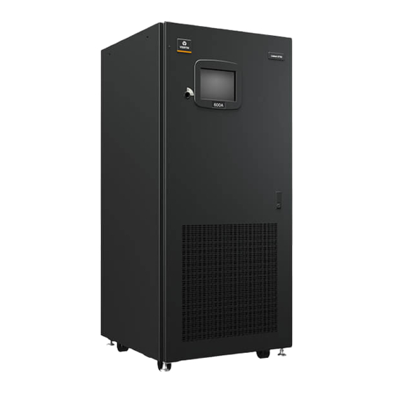
Vertiv Liebert STS2/PDU User Manual (145 pages)
Static Transfer Switch 2/Power Distribution Unit . 250A-800A, Three-Phase, 60 Hz
Brand:
Vertiv
| Category:
Switch
| Size: 10 MB
Table of Contents
Important Safety Instructions
9
Overview of Manual
10
Safety Precautions
11
Unpacking and Inspections
12
Handling Considerations
13
Location Considerations
14
Altitude
15
Locating the Liebert Sts2
16
Power and Control Wiring
17
System Grounding
18
Figure 3 Typical One-Line Diagram of Two Pdus and a Liebert STS2
19
Control Wiring Connections
20
Options
21
Comms Board
22
Remote Source Selection Wiring
23
Input Junction Box Installation—Optional
24
Installation Drawings
25
Figure 5 Outline Drawing: 400 – 600 Amp Liebert STS2
26
Figure 6 Outline Drawing: 800 – 1000 Amp Liebert STS2
27
Figure 7 Outline Drawing: 100 – 250Amp Liebert STS2 with a Key Lockout Switch Option
28
Figure 8 Outline Drawing: 400 – 600 Amp Liebert STS2 with a Key Lockout Switch Option
29
Figure 9 Outline Drawing: 800 – 1000 Amp Liebert STS2 with the Key Lockout Switch Option
30
Figure 10 Seismic Anchor Drawing: 100 – 250 Amp Liebert STS2
31
Figure 11 Seismic Anchor Drawing: 400 – 600 Amp Liebert STS2
32
Figure 12 Seismic Anchor Drawing: 800 – 1000 Amp Liebert STS2
33
Breaker
34
Breakers
35
Breaker
36
Breakers
37
Breaker
38
Figure 18 Electrical Field Connections: 800 – 1000 Amp Liebert STS2 with Dual Output Breakers
39
Figure 19 Control Connection Location Diagram: 100 – 600 Amp Liebert STS2
40
Figure 20 Control Connection Location Diagram: 800 – 1000 Amp Liebert STS2
41
Figure 21 Control Wiring for Remote Source Selection Option
42
Figure 22 Control Wiring for the Programmable Relay Board Option
43
Figure 23 Control Wiring for the Input Contact Isolator Board Option
44
Figure 24 Control Wiring for Comms Board
45
Figure 25 Control Wiring for the Liebert Intellislot Snmp/Web/Modbus 485 Card
46
Figure 26 Control Wiring for the RS-232 Port
47
Figure 27 Outline Drawing for Input Junction Box
48
Figure 28 LED Display
49
Figure 29 Installation Drawing, Seismic Floor Stand 100-250A
50
Figure 30 Installation Drawing, Seismic Floor Stand 100-250A
51
Figure 31 Installation Drawing, Seismic Floor Stand 100-250A
52
Figure 32 Installation Drawing, Seismic Floor Stand 100-250A
53
Figure 33 Installation Drawing, Seismic Floor Stand 400-600A
54
Figure 34 Installation Drawing, Seismic Floor Stand 400-600A
55
Figure 35 Installation Drawing, Seismic Floor Stand 400-600A
56
Figure 36 Installation Drawing, Seismic Floor Stand 400-600A
57
Figure 37 Installation Drawing, Seismic Floor Stand 800-1000A
58
Figure 38 Installation Drawing, Seismic Floor Stand 800-1000A
59
Figure 39 Installation Drawing, Seismic Floor Stand 800-1000A
60
Figure 40 Installation Drawing, Seismic Floor Stand 800-1000A
61
Introduction to Liebert Sts2 Operations
62
Reliability and Agency Requirements
63
Bypass
64
Theory of Operation
65
Emergency Transfer
66
Detailed Component Description
67
Scr's
68
Operating Instructions for the Touchscreen Interface
69
Normal System Startup
70
Figure 42 Source Transfer Screen
71
Enabling Remote Source Selection
72
Figure 43 Gate Board Viewing Slot Locations
73
Bypass Procedures for Source 1
74
Bypass Procedures for Source 2
75
Alarm and Faults
76
Event Log
77
Alarm Notes
78
Table 5 Event Messages
79
Communication Interfaces
81
Connecting and Using a Terminal
82
Configuring the Liebert STS2 Via the Terminal
83
Table 7 Value Types
84
Setting Bitpacked Options with the Terminal
86
Table 9 Binary-Hexadecimal Conversions
87
Setting Event Masks with the Terminal
88
Liebert Sts2 Touchscreen Display
90
Menu Overview
91
Security
92
MIMIC Display
93
User Settings
94
Figure 49 User Settings Dialog Box
95
Figure 50 Source Setpoints
96
System Settings
98
Configuring the Input Contact Isolator Settings
99
Configuring the Programmable Relay Board Settings
100
Figure 53 Programmable Relay Board Dialog Box
101
Saving Your Communications Configurations
102
System ID
103
Logs
104
Source Transfers
105
Operating the Liebert Sts2 Led Display
106
Figure 57 LED Display
107
LED and Push Button Description
108
Key Lockout Switch
109
Manual Transfer / Preferred Source Selection
110
Maintenance Bypass
111
Normal System Shutdown
113
Specifications
114
Grounding
115
System Components
116
Access
117
RS-232 Port
118
Maintenance Bypass
119
Event Message Help Text
120
Maintenance
138
Advertisement
Advertisement
Related Products
Vertiv Liebert STS2
Vertiv Cybex SC 920H
Vertiv Cybex SC 840D
Vertiv AVOCENT SV 340H
Vertiv SCKM185
Vertiv SCKM120
Vertiv SC 840D
Vertiv Cybex SC800 DPHC Series
Vertiv Cybex SC820DPH
Vertiv Cybex SCKM140PP4
Vertiv Categories
UPS
Power Supply
Switch
Power distribution unit
Air Conditioner
More Vertiv Manuals
Login
Sign In
OR
Sign in with Facebook
Sign in with Google
Upload manual
Upload from disk
Upload from URL