Table of Contents
Advertisement
Quick Links
OPERATING AND MAINTENANCE INSTRUCTIONS MANUAL
VE106 and VE107 Groove-N-Go
PIPE/TUBING ROLL GROOVING TOOLS
WARNING
If you need additional copies of any literature, or if you have questions concerning the safe
and proper operation of this tool, contact Victaulic, P.O. Box 31, Easton, PA 18044-0031,
Phone: 1-800-PICK VIC, E-Mail: pickvic@victaulic.com.
REV_D
WARNING
Failure to follow instructions and warnings could result in serious
personal injury, property damage, and/or product damage.
• Before operating or servicing any roll grooving tools, read all
instructions in this manual and all warning labels on the tool.
• Wear safety glasses, hardhat, foot protection, and hearing
protection while working around this tool.
• Save this operating and maintenance manual in a place
accessible to all operators of the tool.
Original Instructions
TM-VE106/107
TM-VE106/107
Advertisement
Table of Contents

Subscribe to Our Youtube Channel
Related Manuals for Victaulic VE106 Groove-N-Go


Summary of Contents for Victaulic VE106 Groove-N-Go
- Page 1 If you need additional copies of any literature, or if you have questions concerning the safe and proper operation of this tool, contact Victaulic, P.O. Box 31, Easton, PA 18044-0031, Phone: 1-800-PICK VIC, E-Mail: pickvic@victaulic.com.
-
Page 3: Table Of Contents
TM-VE106/107 / Operating and Maintenance Instructions Manual TABLE OF CONTENTS Maintenance ..... . 28 Hazard Identification ....4 Parts Ordering Information . -
Page 4: Hazard Identification
. Additional copies of • The use of the word “CAUTION” this manual are available upon request through identifies possible hazards or unsafe Victaulic . practices that could result in personal injury and product or property damage DANGER if instructions, including recommended precautions, are not followed. - Page 5 . safety foot switch is easily accessible to the operator . 10. Use only Victaulic replacement parts and accessories . Use of any other parts may result in a voided warranty, improper operation, and hazardous situations . Refer to the “Parts Ordering Information”...
-
Page 6: Introduction
Victaulic. The Victaulic VE106/VE107 is a manual-feed tool for roll grooving pipe/tubing to receive Victaulic grooved pipe/tubing products . The standard VE106/VE107 tool is supplied with grooving rolls for 11/4–6 inch/42 .4–168 .3 mm... -
Page 7: Power Requirements
TM-VE106/107 / Operating and Maintenance Instructions Manual POWER REQUIREMENTS EXTENSION CORD REQUIREMENTS When pre-wired outlets are not available and DANGER an extension cord must be used, it is important to use the proper cord size (i .e . Conductor Size •... -
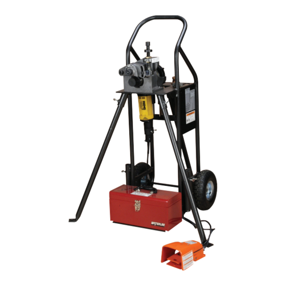
Page 8: Tool Nomenclature
If you need additional copies of any literature, or if you have questions concerning the safe and proper T = Pipe Wall Thickness at Base of Groove operation of any pipe preparation tools, contact Victaulic, P.O. Box 31, Easton, PA 18044-0031, Phone A = Distance from Pipe D = Groove Depth 1-800-PICK VIC, E-Mail: pickvic@victaulic.com. -
Page 9: Tool Dimensions And Specifications
TM-VE106/107 / Operating and Maintenance Instructions Manual TOOL DIMENSIONS AND SPECIFICATIONS 22.00 in/ 559 mm 35.00 in/ 889 mm 32.25 in/ 819 mm 39.50 in/ 1003 mm Plan View Front View 40.50 in/ 1029 mm 48.75 in/ 1238 mm 45.00 in/ 1143 mm * 49.00 in/ 1245 mm... -
Page 10: Tool Setup
TM-VE106/107 / Operating and Maintenance Instructions Manual TOOL SETUP WARNING • DO NOT connect the tool to the electrical source until instructed otherwise. Accidental startup of the tool could result in serious personal injury. The standard VE106/VE107 Groove-N-Go tool is intended for field or shop setup . Before grooving, the adjustable legs must be mounted 3. - Page 11 TM-VE106/107 / Operating and Maintenance Instructions Manual 5. Ensure that the front legs are securely 7a. Level the tool from front to back . NOTE: fastened in the sockets . Lift/tilt the tool into the The top of the tool head table is a good location vertical (upright) position, as shown above .
- Page 12 • DO NOT operate the drive motor without a safety foot switch. If the tool does not contain a safety foot switch, contact Victaulic. Operating the tool without a safety foot 10. Rotate the drive motor switch to the “L”...
-
Page 13: Pre-Operation Checks And Adjustments
“Tool Rating and Roll Selection” section . If the damage grooving rolls, resulting in distorted proper rolls are not installed on the tool, refer to grooves and grooves that are out of Victaulic the “Roll Changing” section . specifications. REV_D... -
Page 14: Pipe Lengths Suitable For Grooving
. Instead of roll grooving those listed in Table 1, are available from a 20-foot (6 .09-m) length of steel pipe and a Victaulic. 4-inch (101 .6-mm) length of steel pipe, follow these steps: 1. Refer to Table 1 and note that for 6-inch diameter steel pipe, the minimum length that should be roll grooved is 10 inches (254 mm) . -
Page 15: Long Pipe/Tubing Lengths
Length of Pipe • Figure 1 shows a typical pipe stand. FIGURE 2 – TRACKING ANGLE • Victaulic offers several pipe stands, such as the VAPS112 and VAPS224. The VAPS112 is suitable for 3/4 to 12-inch/ 26.9 to 323.9-mm sizes. The VAPS224 is suitable for 2 to 24-inch/60.3 to 610-mm... -
Page 16: Groove Diameter Stop Adjustment
TM-VE106/107 / Operating and Maintenance Instructions Manual GROOVE DIAMETER STOP ADJUSTMENT The groove diameter stop must be adjusted for each pipe/tubing size or change in wall thickness . The groove diameter, which is identified as the “C” dimension, is listed under the “Roll Groove Specifications”... - Page 17 TM-VE106/107 / Operating and Maintenance Instructions Manual 6. Locate the groove depth gauges on the tool . Remove the wing nut from the gauge retainer, 4. Ensure that the pipe/tubing end contacts the and select the proper groove depth gauge for the pipe size being grooved .
- Page 18 • Loading and unloading pipe/tubing will 11. If the groove diameter (“C” dimension) is not place your hands close to the rollers. within Victaulic specifications, the diameter stop Keep hands away from the grooving rolls must be adjusted . during operation.
-
Page 19: Grooving Operation
• The drive motor must be operated with a safety foot switch and drive motor are grounded . safety foot switch. If the drive motor does not contain a safety foot switch, contact Victaulic. Operating the tool without a safety foot switch could result in serious personal injury. - Page 20 TM-VE106/107 / Operating and Maintenance Instructions Manual 5. Using the feed ratchet (provided), rotate the feed screw counterclockwise to move the upper roll to the fully up position . WARNING 6. Insert a length of pipe/tubing that is the Grooving rolls can crush or correct size and thickness onto the lower roll .
- Page 21 TM-VE106/107 / Operating and Maintenance Instructions Manual 8. Rotate the feed screw clockwise to bring the upper roll into firm contact with the pipe/tubing . Continue to support the pipe, or use a pipe stand for long pipe/tubing lengths . Refer to the “Long Pipe/Tubing Lengths”...
- Page 22 TM-VE106/107 / Operating and Maintenance Instructions Manual NOTICE WARNING • Groove light-wall pipe at a moderate rate • DO NOT place hands inside the pipe/ by forming grooves uniformly in 5 to 10 tubing end or in the area of the grooving pipe rotations.
-
Page 23: Roll Changing
TM-VE106/107 / Operating and Maintenance Instructions Manual ROLL CHANGING WARNING • Before making any tool adjustments, always disconnect the power cord from the electrical source. Accidental startup of the tool could result in serious personal injury. The VE106/VE107 Groove-N-Go is designed with rolls to accommodate several pipe sizes, which eliminates the need for frequent roll changes . - Page 24 TM-VE106/107 / Operating and Maintenance Instructions Manual 5. Using a punch and hammer (these tools are not supplied), tap the lower roll/main shaft out from the rear of the tool, as shown above . 3. Remove the drive key from the rear of the shaft .
-
Page 25: Upper Roll Removal
TM-VE106/107 / Operating and Maintenance Instructions Manual UPPER ROLL REMOVAL The same upper roll is used for standard grooving of carbon steel pipe and stainless steel pipe . When preparing to groove copper tubing or pipe to “ES” specifications, the upper roll for carbon steel/stainless steel pipe must be removed and the appropriate upper roll must be installed . -
Page 26: Upper Roll Installation
TM-VE106/107 / Operating and Maintenance Instructions Manual UPPER ROLL INSTALLATION LOWER ROLL/MAIN SHAFT INSTALLATION 1. Select the proper upper roll for the pipe size and material to be grooved . Refer to the “Tool 1. Select the proper lower roll/main shaft for the Rating and Roll Selection”... - Page 27 TM-VE106/107 / Operating and Maintenance Instructions Manual 4. Install the lower roll/main shaft into the tool head . While maintaining a grip on the knurled end (lower roll) of the main shaft, ensure that the flats on the drive end of the main shaft align with the flats in the drive motor .
-
Page 28: Maintenance
Preventive maintenance during operation will pay for itself in repair and operating savings . Replacement parts must be ordered from Victaulic to ensure proper and safe operation of the tool . 1. After every two hours of operation, apply a No . - Page 29 TM-VE106/107 / Operating and Maintenance Instructions Manual 2. Apply grease underneath the toggle pad . 4. Apply grease to the locations in which the roll arm slides against the tool body . 3. Apply grease to the ball-and-socket joint of the toggle pad .
-
Page 30: Parts Ordering Information
. PARTS ORDERING INFORMATION When ordering parts, the following information is required for Victaulic to process the order The Victaulic VAPS112 is a portable, adjustable, and send the correct part(s) . Request the roller-type pipe stand that contains four legs RP-VE106/107 Repair Parts List for detailed for additional stability . - Page 31 2 to 24-inch/60 .3 to 610 .0-mm pipe sizes . Contact Victaulic for details . OPTIONAL ROLLS The following optional rolls are available for purchase . Contact Victaulic for details . • Lower Roll/Main Shaft for Grooving 1 1/4 – 6-inch/42 .4 – 168 .3-mm Schedule...
-
Page 32: Troubleshooting
TM-VE106/107 / Operating and Maintenance Instructions Manual TROUBLESHOOTING PROBLEM POSSIBLE CAUSE SOLUTION Pipe will not stay in grooving Incorrect pipe positioning of long pipe. Refer to “Long Pipe/Tubing Lengths” on page 15. rolls. Lower roll/main shaft and pipe are not Turn the drive motor switch to the opposite rotation position. - Page 33 Install the correct rolls. Refer to “Tool Rating and Roll Selection” on specifications. installed on the tool. page 34. In the event of tool malfunction outside the scope of the troubleshooting section, contact Victaulic Engineering Services for assistance. REV_D TM-VE106/107_33...
-
Page 34: Tool Rating And Roll Selection
In addition, the following pipe sizes may be roll grooved: 76.1 mm; 108.0 mm; 127.0 mm; 133.0 mm; 139.7 mm; 152.4 mm; 159.0 mm; and 165.1 mm. Contact Victaulic for details. STANDARD ROLLS FOR SCHEDULES 5S AND 10S STAINLESS STEEL PIPE –... -
Page 35: Astm Drawn Copper Tubing
TM-VE106/107 / Operating and Maintenance Instructions Manual CTS US STANDARD – ASTM DRAWN COPPER TUBING – COLOR-CODED COPPER Tube Size Dimensions - inches/millimeters Copper Copper Tubing Wall Thickness Actual Nominal Outside Diameter Roll Part Size inches inches/mm Minimum Maximum Numbers 2.125 0.042 0.083... -
Page 36: Explanation Of Critical Roll Groove Dimensions
NOTICE FOR STANDARD COUPLINGS WITH RATINGS ON LIGHT-WALL STAINLESS STEEL PIPE: • Victaulic RX rolls MUST be used when roll grooving light-wall stainless steel pipe for use with standard couplings. Pipe Outside Diameter – Nominal NPS Pipe Size (ANSI B36.10) and Basic Metric Pipe Size (ISO 4200) –... - Page 37 “T” Dimension – The “T” dimension is the lightest grade (minimum nominal wall thickness) of pipe that is suitable for cut or roll grooving . Pipe that is less than the minimum nominal wall thickness for cut grooving may be suitable for roll grooving or adapted for Victaulic couplings by using Vic-Ring ®...
-
Page 38: Roll Groove Specifications
TM-VE106/107 / Operating and Maintenance Instructions Manual REV_D TM-VE106/107_38... -
Page 39: Endseal Couplings
TM-VE106/107 / Operating and Maintenance Instructions Manual REV_D TM-VE106/107_39... -
Page 40: Hard-Drawn Copper Tubing
TM-VE106/107 / Operating and Maintenance Instructions Manual REV_D TM-VE106/107_40... -
Page 41: Copper Tubing
TM-VE106/107 / Operating and Maintenance Instructions Manual REV_D TM-VE106/107_41... - Page 43 TM-VE106/107 / Operating and Maintenance Instructions Manual REV_D TM-VE106/107_43...
- Page 44 TM-VE106/107 OPERATING AND MAINTENANCE INSTRUCTIONS MANUAL VE106 and VE107 Groove-N-Go UPDATED 04/2016 TM-VE106/107 3736 REV D RM00PRG100 VICTAULIC IS A REGISTERED TRADEMARK OF VICTAULIC COMPANY. © 2016 VICTAULIC COMPANY. ALL RIGHTS RESERVED.
Need help?
Do you have a question about the VE106 Groove-N-Go and is the answer not in the manual?
Questions and answers