Table of Contents
Advertisement
Quick Links
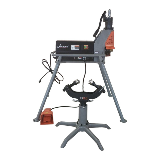
OPERATING AND MAINTENANCE INSTRUCTIONS MANUAL
RG3212 Roll Grooving Tool
WARNING
If you need additional copies of any literature, or if you have questions concerning the safe
and proper operation of this tool, contact Victaulic, P.O. Box 31, Easton, PA 18044-0031,
Phone: 1-800-PICK-VIC, E-Mail: pickvic@victaulic.com.
REV_B
WARNING
Failure to follow instructions and warnings could result in death,
serious personal injury, property damage, and/or product damage.
• Before operating or servicing any grooving tools, read all
instructions in this manual and all warning labels on the tool.
• Wear safety glasses, hardhat, foot protection, and hearing
protection while working around this tool.
• Save this operating and maintenance manual in a place
accessible to all operators of the tool.
Original Instructions
TM-RG3212
OGS
Advertisement
Table of Contents

Related Manuals for Victaulic RG3212


Summary of Contents for Victaulic RG3212
- Page 1 If you need additional copies of any literature, or if you have questions concerning the safe and proper operation of this tool, contact Victaulic, P.O. Box 31, Easton, PA 18044-0031, Phone: 1-800-PICK-VIC, E-Mail: pickvic@victaulic.com.
-
Page 3: Table Of Contents
TM-RG3212 / Operating and Maintenance Instructions Manual TABLE OF CONTENTS Hazard Identification ....4 Operator Safety Instructions ... . 4 Introduction . -
Page 4: Hazard Identification
INSTRUCTIONS Definitions for identifying the various hazard levels are provided below . The RG3212 is designed for the sole purpose of roll grooving pipe . These instructions must This safety alert symbol indicates be read and understood by each operator important safety messages . - Page 5 TM-RG3212 / Operating and Maintenance Instructions Manual DANGER CAUTION Avoid using the tool in potentially This tool is designed ONLY for dangerous environments. Do not expose roll grooving pipe sizes, materials, and the tool to rain, and do not use the tool in wall thicknesses listed in the “Tool...
-
Page 6: Introduction
. Tool with Motor and Hydraulic Pump Handle CAUTION Foot Switch • The RG3212 should only be used for roll PS3212 Pipe Stand grooving pipe designated in the “Tool Roll Set for 2–3.5-inch Pipe - Ratings for Steel Pipe” section of this Original Groove System Specification manual. -
Page 7: Power Requirements
Extension cords must meet all applicable local region . codes and facility rules for safe and proper use . The RG3212 tool must be grounded properly in accordance with all local and national electrical Cord Lengths code requirements . -
Page 8: Tool Nomenclature
TM-RG3212 / Operating and Maintenance Instructions Manual TOOL NOMENCLATURE Locking Nut Depth Adjuster Nut Hydraulic Pump Valve Hydraulic Hydraulic Cylinder Pump Handle Power Switch Upper Roll Power Cord PS3212 Pipe Stand Foot Switch REV_B... -
Page 9: Tool Dimensions
TM-RG3212 / Operating and Maintenance Instructions Manual TOOL DIMENSIONS TOOL SPECIFICATIONS Tool weight: 302 pounds/137 kg Voltage: 120-volt, single phase Frequency: 60 Hz 15A Capacity of oil reservoir: 5 fl oz/150 ml 51.2 inches 1300 mm 43.3 inches 1100 mm 32.3 inches... -
Page 10: Pre-Operation Adjustments
2. Raised internal and external weld beads and seams must be ground flush with the pipe Every RG3212 tool is checked and tested at surface 2 inches/50 mm back from the pipe the factory prior to shipment . Before grooving, ends . -
Page 11: Long Pipe Lengths
TM-RG3212 / Operating and Maintenance Instructions Manual Table 1- Carbon Steel and Schedule 40 Stainless Steel Pipe Lengths Suitable for Grooving without a Pipe Stand Length inches Nominal Size inches or mm 2 – 4 inches 4 1/2 – 5 inches 152.4 mm... -
Page 12: Groove Diameter Stop Adjustment
TM-RG3212 / Operating and Maintenance Instructions Manual CAUTION • Right-to-left tracking angle must be kept to a minimum. Keep the pipe as centered as possible on the lower roll. • Verify that the tool is level. The pipe may not track properly if the back end of the pipe is higher than the end being grooved. - Page 13 TM-RG3212 / Operating and Maintenance Instructions Manual 8. Groove the sample pipe by following the “Grooving Operation” section . Continue the grooving operation until the depth adjuster nut contacts the tool head . Allow the pipe to rotate an additional one to two turns to ensure groove Locking Nut completion .
-
Page 14: Grooving Operation
. This will raise the slide and upper roll to their highest positions . CAUTION • RG3212 tools are designed ONLY for roll grooving pipe sizes and wall thicknesses outlined in the “Tool Rating and Roll Selection” section. - Page 15 TM-RG3212 / Operating and Maintenance Instructions Manual NOTE: If the pipe does not remain against the WARNING lower roll, stop the tool by turning the switch to the “OFF” position . Verify that the pipe is level Grooving rolls can crush and positioned properly .
-
Page 16: Lower Roll Removal
TM-RG3212 / Operating and Maintenance Instructions Manual LOWER ROLL REMOVAL WARNING WARNING • DO NOT strike the lower roll/ main shaft with a hammer or • Always disconnect the tool from the other blunt object. electrical source before making any tool Striking the lower roll/main adjustments. -
Page 17: Upper Roll Removal
TM-RG3212 / Operating and Maintenance Instructions Manual UPPER ROLL REMOVAL WARNING • Always disconnect the tool from the electrical source before making any tool adjustments. Accidental startup of tool may result in serious personal injury. 3. While supporting the upper roll, remove the upper shaft from the slide/upper roll holder by pulling it straight outward . -
Page 18: Upper Roll Installation
TM-RG3212 / Operating and Maintenance Instructions Manual UPPER ROLL INSTALLATION LOWER ROLL INSTALLATION Clean the upper shaft to remove any dirt Clean the main shaft and lower roll bore to before installation of the upper roll . Inspect the remove any dirt before installation of the lower roll . -
Page 19: Maintenance
TM-RG3212 / Operating and Maintenance Instructions Manual MAINTENANCE Fill Hydraulic System WARNING • Always disconnect the tool from the electrical source before making any tool adjustments. Accidental startup of tool may result in serious personal injury. Prior to the start of each shift, verify that the tool Hydraulic and roll sets are clean . -
Page 20: Ps3212 Pipe Stand
. PARTS ORDERING INFORMATION When ordering parts, the following information is required for Victaulic to process the order and send the correct part(s) . Parts can be ordered by calling 1-800-PICK-VIC . Tool Model Number Tool Serial Number 2. -
Page 21: Troubleshooting
Hydraulic pump is low on oil. Refer to the “Maintenance” section. Pipe is beyond tool’s wall thickness capability. Refer to the “Tool Rating and Roll Selection” section. In the event of tool malfunction outside the scope of the troubleshooting section, contact Victaulic for assistance. REV_B... -
Page 22: Explanation Of Critical Roll Groove Dimensions
TM-RG3212 / Operating and Maintenance Instructions Manual EXPLANATION OF CRITICAL ROLL GROOVE DIMENSIONS WARNING • Pipe dimensions and groove dimensions must be within the tolerances specified in the tables on the following pages to ensure proper joint performance. Failure to follow these specifications could cause joint failure, resulting in serious personal injury and/or property damage. - Page 23 . NOTICE • Coatings that are applied to the interior surfaces of Victaulic grooved pipe couplings must not exceed 0.010 inch/0.25 mm. This includes bolt pad mating surfaces. • In addition, the coating thickness applied to the gasket-sealing surface and within the groove on the pipe exterior must not exceed 0.010 inch/0.25 mm.
-
Page 24: Tool Rating And Roll Selection
TM-RG3212 / Operating and Maintenance Instructions Manual TOOL RATING AND ROLL SELECTION ORIGINAL GROOVE SYSTEM (OGS) ROLLS FOR CARBON STEEL AND STAINLESS STEEL PIPE Pipe Size Dimensions - inches/millimeters Actual Steel Pipe Stainless Steel Pipe Outside Wall Thickness † Wall Thickness... - Page 25 TM-RG3212 / Operating and Maintenance Instructions Manual This page intentionally blank REV_B...
-
Page 26: Roll Groove Specifications
TM-RG3212 / Operating and Maintenance Instructions Manual REV_B... - Page 27 TM-RG3212 / Operating and Maintenance Instructions Manual REV_B...
- Page 28 OPERATING AND MAINTENANCE INSTRUCTIONS MANUAL RG3212 Roll Grooving Tool UPDATED 03/2021 TM-RG3212 13505 REV B VICTAULIC IS A REGISTERED TRADEMARK OF VICTAULIC COMPANY AND/OR ITS AFFILIATED ENTITIES IN THE UNITED STATES AND/OR OTHER COUNTRIES. © 2021 VICTAULIC COMPANY. ALL RIGHTS RESERVED.
Need help?
Do you have a question about the RG3212 and is the answer not in the manual?
Questions and answers